
Multi-tubular reactor, design and manufacturing method of multi-tubular reactor

A manufacturing method and technology for reaction tubes, which are applied in chemical instruments and methods, preparation of organic compounds, preparation of carboxylate, etc., can solve the problem that the difference of heat medium is easy to increase, the heat conduction state of reaction tube changes, and the flow resistance of heat medium increases. And other issues

Active Publication Date: 2017-11-21
SUMITOMO CHEM CO LTD
View PDF2 Cites 0 Cited by
  • Summary
  • Abstract
  • Description
  • Claims
  • Application Information

AI Technical Summary

Problems solved by technology

[0008] In addition, Patent Document 1 raises the following problem: in the case of a large number of reaction tubes, the difference in the flow pattern of the heat medium tends to be large in the fixed-bed multi-tubular reactor, and if the flow pattern is different, the reaction The thermal conductivity of the tube changes
[0011] However, although the lack of a circular baffle plate can be adopted in a small multi-tubular reactor (the number of reaction tubes is less than 10,000), it cannot be used in a large multi-tubular reactor (the number of reaction tubes is less than 10,000). When the number is more than 10,000), the flow resistance of the heat medium flowing in the casing increases
Therefore, in large-scale multi-tubular reactors, less circular baffle plates are used, and ring-shaped baffle plates (that is, disk-ring type baffle plates) are mostly used, but for properly controlling the large-scale For the reaction in a multi-tubular reactor, it is difficult to guess where to measure the temperature of the reaction tubes based on the technique of Patent Document 1.

Method used


Image

  • Multi-tubular reactor, design and manufacturing method of multi-tubular reactor
  • Multi-tubular reactor, design and manufacturing method of multi-tubular reactor
  • Multi-tubular reactor, design and manufacturing method of multi-tubular reactor

Examples


Embodiment

[0194] In an embodiment of the present invention, in a multi-tubular reactor in which a plurality of reaction tubes are arranged in the above-mentioned triangle, the flow state of the heat medium is confirmed by numerical simulation.

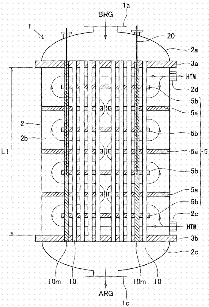
[0195] In this numerical simulation, for example, as figure 2 As shown, in the case where a disc-annular baffle plate 5, especially an annular baffle plate 5a, is provided in a cylindrical shell, in order to confirm the flow toward the radial direction that can be generated in the reactor, it is confirmed that The flow conditions of the heat medium at the section of the multi-tubular reactor are analyzed.

[0196] It should be noted that, in the case of arranging a plurality of reaction tubes in a triangular arrangement, since an axisymmetric flow can be formed with respect to the central axis of the cylindrical shell of the reactor, as Figure 4 As shown, in this numerical simulation, it is not carried out in the entire section of the multi-tub...


PUM

PropertyMeasurementUnit
densityaaaaaaaaaa

Abstract

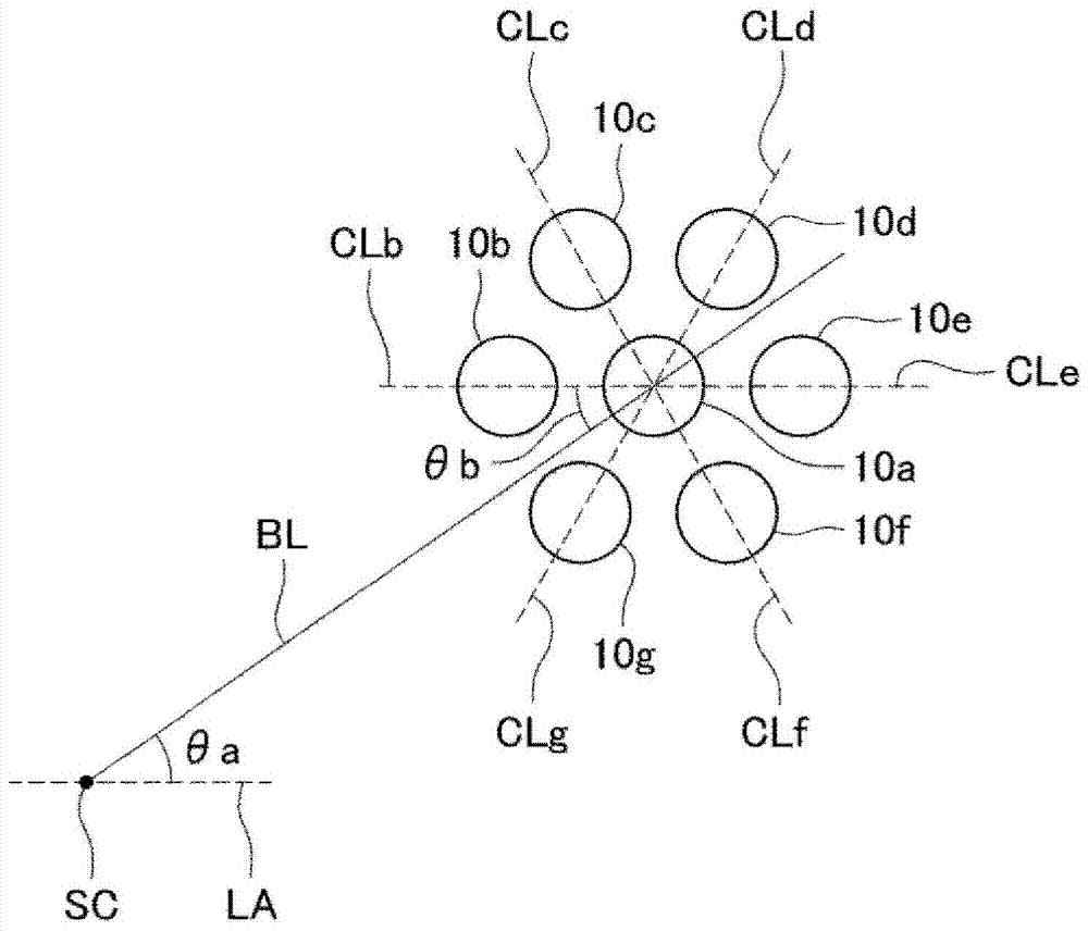
The object of the present invention is to provide a multi-tubular reactor, the design and manufacturing method of the multi-tubular reactor, which can properly control the reaction when producing substances accompanied by exothermic and endothermic reactions , to prevent the formation of hot or cold spots. The multi-tubular reactor (1) of the present invention comprises a cylindrical shell (2), a plurality of reaction tubes (10) arranged in the shell, and a disk-annular barrier plate (5), the multiple The reaction tubes (10) are arranged in a triangular configuration, and one or more of the plurality of reaction tubes (10) is a temperature-measuring reaction tube provided with a thermometer (20). In the section perpendicular to the central axis of (2), the straight line (BL) connecting the central axis of the temperature-measuring reaction tube and the central axis of the shell (2) and the central axis of the temperature-measuring reaction tube adjacent to the The straight line (CL) of the central axis of at least one adjacent reaction tube of the thermometry reaction tube forms an angle of 0-15 degrees.

Description

technical field [0001] The present invention relates to a multi-tubular reactor, the design of the multi-tubular reactor and a method for its manufacture. More specifically, it relates to a multi-tubular reactor having a cylindrical shell, a plurality of reaction tubes arranged in the shell, and disc-and-doughnut type baffle plates, and the multi-tube reactor The design of the reactor and its fabrication method. Background technique [0002] For a multi-tubular reactor (so-called shell-and- In a tube) type reactor), for example, a catalyst is preliminarily filled in a reaction tube, a raw material gas is supplied to the reaction tube, and the raw material gas is circulated in one direction in the reaction tube, and the raw material gas is reacted, so that the target substance ( Hereinafter, it may also be referred to as the generation of "target substance" or "target product"). [0003] In the reaction of the raw material gas in the reaction tube, the reaction temperature...

Claims


Application Information

Patent Timeline
Patent Type & Authority Patents(China)
IPC IPC(8): B01J8/06C07C45/35C07C45/37C07C47/22C07C51/23C07C51/25C07C57/055
CPCC07C45/35C07C51/252B01J2208/00044B01J2208/00221B01J2208/0023Y10T29/49828B01J8/067C07C47/22C07C57/04B01J8/001C07C45/37C07C45/34C07C51/21B01J2208/00212B01J2208/065
Inventor 山内真吾高元保
Owner SUMITOMO CHEM CO LTD
Learn More