Drive clutch self-priming device

A technology of self-priming device and separation device, applied in the direction of driving pump, pump device, machine/engine, etc., can solve the problems of unfavorable pump mass production motor after-sales maintenance, user disapproval, and many preparations, etc., to achieve convenient standardized design and Simple and reliable production, control elements, and simple flow regulation

Inactive Publication Date: 2015-01-14
辽宁格瑞特泵业有限公司
View PDF11 Cites 4 Cited by
  • Summary
  • Abstract
  • Description
  • Claims
  • Application Information

AI Technical Summary

Problems solved by technology

The original ordinary self-priming pumps are due to: 1. The self-priming height is low (1-4 meters); 2. The self-priming time is long (5 minutes or even longer); 3. The reliability of self-priming is not strong, and it often sucks No medium; 4. In order to realize the self-priming function, backflow is required, so that the pump efficiency is low; 5. It is not suitable for outdoors in winter in the north; 6. The internal return hole is often blocked, and problems such as frequent failures and frequent maintenance are gradually withdrawn from the self-priming pump market.
There are also new self-priming pumps on the market (self-priming devices and electronic control systems in addition to centrifugal pumps): 1. Many preparations and complex structures
2. The electrical components are easily damaged, causing the pump to not self-prime normally
3. High cost, 4. Cannot be used without power supply and many other problems
Compared with these self-priming pumps, the patent number of "one machine with double belt self-priming pump": ZL 201420082035.X and "a new type of chemical self-priming pump" patent number: ZL 201420082037.9 overcomes the shortcomings of the above-mentioned self-priming pump, and has: 1. Compared with the new self-priming pump, the self-priming device and the centrifugal pump are driven by a motor or diesel engine, without the need for an electrical control system, the overall structure is simpler and more compact, the cost is lower, the performance is stable, and the failure rate is low; 2. The self-priming time is short , strong capacity, the maximum self-priming height can reach 7 meters; 3. There is no medium in the self-priming pump casing and pipeline, good antifreeze performance, suitable for use in northern winter, etc., but there are still: 1. The overall length of the vacuum pumping device is relatively long Large, heavy, directly installed on the shaft of the motor or centrifugal pump, the standard centrifugal pump or motor has changed a lot, which is not conducive to the mass production of the pump and the after-sales maintenance of the motor; 2. It will affect the structure of the motor and the pump. It has a certain influence on the overall structure and shaft strength of the pump and motor; 3. Due to the different specifications of the motor shaft and the pump shaft of the centrifugal pump, the shaft diameter of the drive shaft varies greatly. The vacuum device or pulley is directly installed on the drive shaft. The shaft diameter must be It is compatible with the shaft diameter of the pump or motor, which is not conducive to the standardized design and production of vacuum pumping devices; 4. Some users do not approve of the transmission mode of belt drive, etc.

Method used


Image

  • Drive clutch self-priming device
  • Drive clutch self-priming device
  • Drive clutch self-priming device

Examples


Embodiment Construction

[0016] The concrete implementation of the present invention will be further described below in conjunction with accompanying drawing:

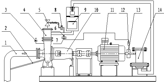
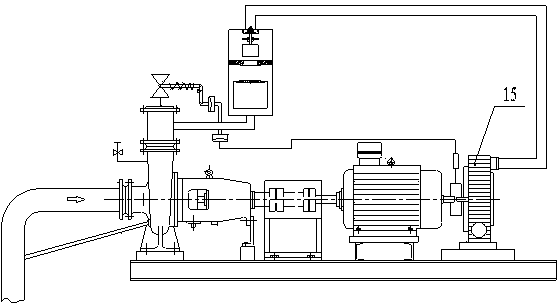
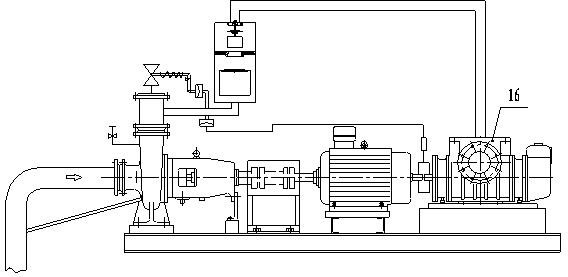
[0017] attached by figure 1 It can be seen that the self-priming device adopts a double-shaft motor, and there is a shaft at the front and rear ends of the motor. The front shaft of the motor drives the centrifugal pump 10, and the rear shaft is connected to the clutch 13 and drives the vacuum device to vacuum, wherein the vacuum device includes a diaphragm type vacuum device. 12. Various vacuuming equipment including gas ring vacuum pump 13 and Roots pump 14. There are two ways of driving between the motor shaft and the vacuum device: the clutch is directly mounted on the motor shaft to drive the vacuum device or the motor is connected to the clutch through a coupling to drive the vacuum device.

[0018] The inlet of the centrifugal pump 10 is connected to the suction pipeline 1, the outlet is provided with an outlet connecting pipe fitting...


PUM


Abstract

The invention provides a novel drive clutch self-priming device mainly applied to lifting of medium liquid. The drive clutch self-priming device is technically characterized in that a double-shaft motor is adopted, each of the front and rear ends of the motor is provided with one shaft, the front shaft is connected with a centrifugal pump, a rear shaft is connected with a vacuumizing device through a clutch, an outlet of the centrifugal pump is provided with an outlet connection pipe fitting which is connected with an outlet self-priming valve and a clutch separation pipeline, and the clutch separation pipeline is connected with a clutch separation device which is connected with the clutch. The drive clutch self-priming device has the advantages that the self-priming device and the centrifugal pump are driven by one motor or diesel engine, no electric control system is needed, and accordingly the device is simpler and more compact in integral structure, lower in manufacturing cost, stable in performance and low in failure rate; a diaphragm type vacuumizing device, a gas ring vacuum pump, a roots pump and the like can serve as the vacuumizing device, and the drive clutch self-priming device is suitable for different working conditions of high flow, toxicity, harmfulness and the like.

Description

technical field [0001] The invention relates to a new type of driving clutch self-priming device, especially a self-priming device that drives a centrifugal pump and a vacuum device at the same time by a motor, and can automatically complete the lifting of the medium without an electric control system. Put it on the working condition and use it. Background technique [0002] With the continuous improvement of self-priming pump technology, its safety and stability are getting higher and higher, and the application range of self-priming pumps in lifting working conditions under medium liquid is becoming wider and wider. The original ordinary self-priming pumps are due to: 1. The self-priming height is low (1-4 meters); 2. The self-priming time is long (5 minutes or even longer); 3. The reliability of self-priming is not strong, and it often sucks No medium; 4. In order to realize the self-priming function, backflow is required, so that the pump efficiency is low; 5. It is not...

Claims


Application Information

Patent Timeline
Patent Type & Authority Applications(China)
IPC IPC(8): F04D9/04F04D13/06
CPCF04D9/04F04D13/06
Inventor 崔正军苏循德赵锦文李学龙王玉霞霍素梅
Owner 辽宁格瑞特泵业有限公司
Why Eureka
Try Eureka