Metal cavity broadband antenna

A technology of metal cavity and broadband antenna, which is applied in the direction of antenna, antenna array, radiating element structure, etc., can solve the problems of high profile of printed vibrator antenna array, low heat conduction of antenna array, narrow impedance bandwidth, etc., to achieve the benefit of static electricity The effect of discharge protection design, reduction of processing process, and reduction of processing difficulty

Active Publication Date: 2015-01-14
CHINA ELECTRONIC TECH GRP CORP NO 38 RES INST
View PDF3 Cites 10 Cited by
  • Summary
  • Abstract
  • Description
  • Claims
  • Application Information

AI Technical Summary

Problems solved by technology

The printed dipole antenna array has a high profile, requires a support structure, and is relatively complicated to assemble when forming a planar array
Ordinary microstrip patch antennas have the disadvantage of narrow impedance bandwidth. Researchers have done a lot of research on the impedance bandwidth of widened microstrip antennas. The typical methods are: 1. Using multi-layer patches, especially double Multi-layer patch antenna, but the multi-layer dielectric board will introduce the problem of glue selection and processing technology for the bonding of different material dielectric boards. The difference in thermal expansion coefficient of different materials will cause the thermal deformation of the entire antenna, which is still a problem for spaceborne SAR antennas. There is the problem of low thermal conductivity of the antenna array; 2. The microstrip patch antenna loaded with various slots (such as: E-slot, U-slot, etc.) in the form of coaxial feed can also increase the impedance bandwidth of the microstrip antenna. However, the thickness of the dielectric plate of these antenna units is usually thick, which increases the weight of the antenna; 3. Other electromagnetically coupled feed microstrip patch antennas such as L-shaped microstrips, terminal loading, and cavity-backed microstrip patch antennas are all have the same flaws as above
Although the microstrip antenna has achieved broadband, an inherent feature of the microstrip antenna itself limits its application, that is, the material itself has low rigidity, and it needs structural plate supports or structural supports of the platform itself. A series of problems such as processing, thermal deformation, heat conduction, etc.

Method used


Image

  • Metal cavity broadband antenna
  • Metal cavity broadband antenna
  • Metal cavity broadband antenna

Examples


Embodiment 1

[0031] Metal cavity broadband antenna working in X-band wavelength 25.6~41.1mm, center frequency wavelength λ 0 It is 31.58mm, the center frequency is 9.5GHz, the lower frequency is 7.3GHz, and the upper frequency is 11.7GHz.

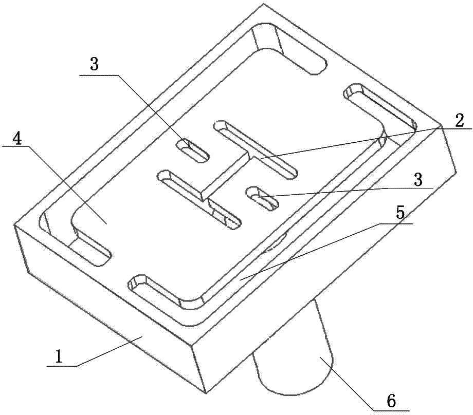
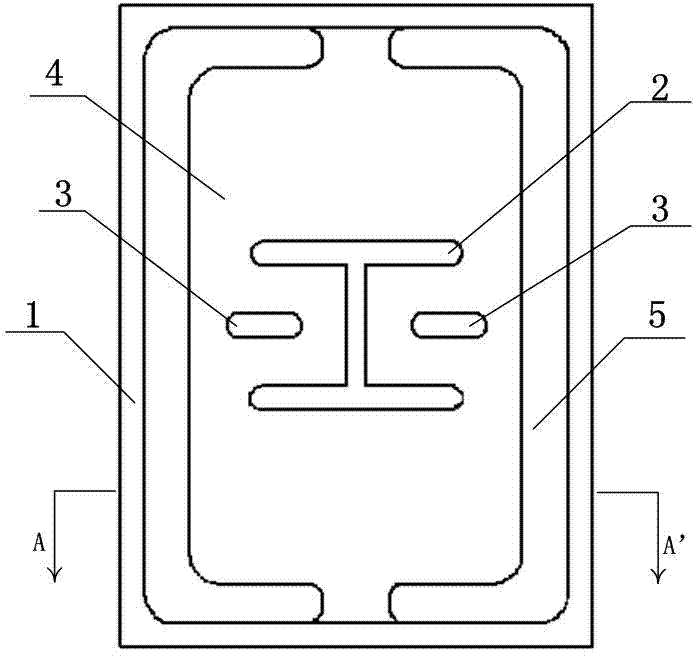
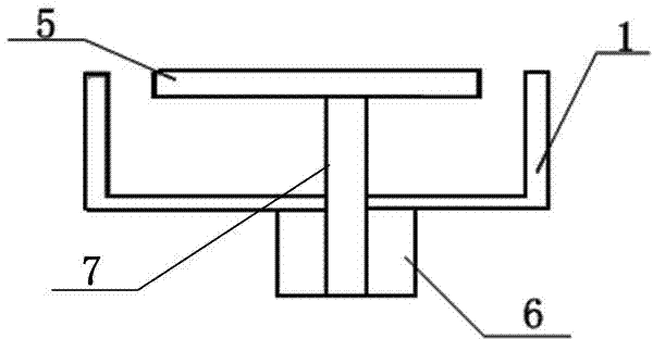
[0032] see figure 1 , figure 2 and image 3 , the metal cavity broadband antenna is a flat box-shaped hollow metal cavity 1, the top middle of the metal cavity 1 is provided with an I-shaped seam 2, the two ends of the I-shaped seam 2 are horizontal seams, and the middle is a vertical seam; Both sides of the middle part of the seam 2 are symmetrically provided with a line seam 3, and the I-shaped seam 2 and the line seam 3 on both sides are radial seams. A coaxial connector 6 is installed on the bottom of the metal cavity 1 , and the inner conductor 7 of the coaxial connector 6 extends into the metal cavity 1 and is connected to the inner top of the metal cavity 1 .

[0033] see Figure 4 and Figure 5 , the inner dimension of metal cavity 1: len...

Embodiment 2

[0039] see Figure 12 , this embodiment is extended from Embodiment 1, and is mainly aimed at the two-dimensional scanning planar phased array antenna required in practical applications.

[0040] The planar array antenna consists of 4×4 metal cavity broadband antennas in Embodiment 1, 16 metal cavity broadband antenna units are arranged in two-dimensional expansion, and the adjacent side walls of adjacent metal cavity broadband antennas are common walls (Adjacent cavities share metal walls); the 4×4 planar array antenna can be processed as a unit module of a planar phased array antenna. The working frequency of the antenna array is 7.3~11.7GHz, working in the X-band with a wavelength of 25.6~41.1mm, and the center frequency wavelength is λ 0 It is 31.58mm.

[0041] According to actual engineering needs or actual processing capabilities, this example can also be extended to a unit module of a planar phased array antenna composed of 8×8 or 16×16 antennas in Embodiment 1.


PUM


Abstract

The invention relates to a metal cavity broadband antenna. According to the basic structure, the metal cavity broadband antenna comprises a flat-box-shaped hollow metal cavity with gaps formed in the top and a coaxial connector. The gaps formed in the upper surface of the metal cavity comprise the I-shaped gap in the middle of the top of the metal cavity, the linear gaps in the two sides of the top of the metal cavity, and technological gaps in the two sides of the metal cavity in the length direction in the shape of []. An inner conductor of the coaxial connector stretches into the metal cavity and is connected with the inner top of the metal cavity. The integrated single metal cavity structure is adopted for the metal cavity broadband antenna and thus is simple in structure, and the antenna machining difficulty is reduced. The single metal material is adopted, so that hidden danger of deformation and layer disengagement caused by different expansion coefficients of multiple materials is eliminated. Because the metal material is good in thermal conductivity and electrical conductivity, thermal control design and electrostatic protection of a satellite-borne phased-array antenna are facilitated. The metal cavity and the gaps are all made full use of, and thus the broadband performance of the antenna is achieved. The profile of the antenna is low, when the antennas are used for combining a planar antenna array, the planar antenna array is of a honeycomb structure, and the metal cavity broadband antenna has the advantage of being high in structural strength.

Description

technical field [0001] The invention belongs to the technical field of antennas, in particular to a metal cavity broadband antenna. Background technique [0002] Broadband antennas are increasingly used in military and civilian applications. At the same time, in some specific applications, there are special requirements for antennas such as volume, weight, efficiency and environmental adaptability. For example: for aircraft / satellite platforms, antennas are required to have a thin profile, light weight, high efficiency and meet certain environmental application conditions. [0003] There are many types of radiating antennas suitable for planar antenna arrays, mainly waveguide slot antennas, open waveguide antennas, printed dipole antennas, and microstrip patch antenna arrays. The waveguide slot antenna is usually a linear array or an area array containing multiple radiating elements, which is used in antenna arrays with centralized feeding or sub-array feeding, and is not ...

Claims


Application Information

Patent Timeline
Patent Type & Authority Applications(China)
IPC IPC(8): H01Q1/36H01Q21/00
Inventor 孙立春汪伟张洪涛金谋平张智慧
Owner CHINA ELECTRONIC TECH GRP CORP NO 38 RES INST
Why Eureka
Try Eureka