
A spring hydraulic type riser string suspension device and suspension method

A spring hydraulic and suspension device technology, applied in earthwork drilling, wellbore/well parts, etc., can solve the problems of rig time occupation, poor operability, difficult operation, etc., to ensure functional reliability and stability, and avoid dynamic Compression, Manipulative Effects

Active Publication Date: 2017-07-21
CHINA NAT OFFSHORE OIL CORP +1
View PDF10 Cites 0 Cited by
  • Summary
  • Abstract
  • Description
  • Claims
  • Application Information

AI Technical Summary

Problems solved by technology

At present, there is no suspension device specially suitable for risers. The suspension of risers is usually completed with the installation tools of the riser. Operation, operation procedures are complicated and time-consuming, and operability is poor in emergency situations
In addition, because soft suspension can relieve the stress state of the string, soft suspension is the preferred suspension method in most cases. However, conventional riser installation tools or suspension tools generally need to be installed with telescopic sub-joints to achieve soft suspension. The installation of the pup joint is cumbersome, takes up the time of the rig, and is not easy to operate under emergency conditions

Method used


Image

  • A spring hydraulic type riser string suspension device and suspension method
  • A spring hydraulic type riser string suspension device and suspension method
  • A spring hydraulic type riser string suspension device and suspension method

Examples


Embodiment Construction

[0014] The present invention will be described in detail below in conjunction with the accompanying drawings and embodiments.

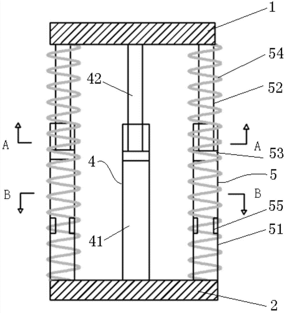
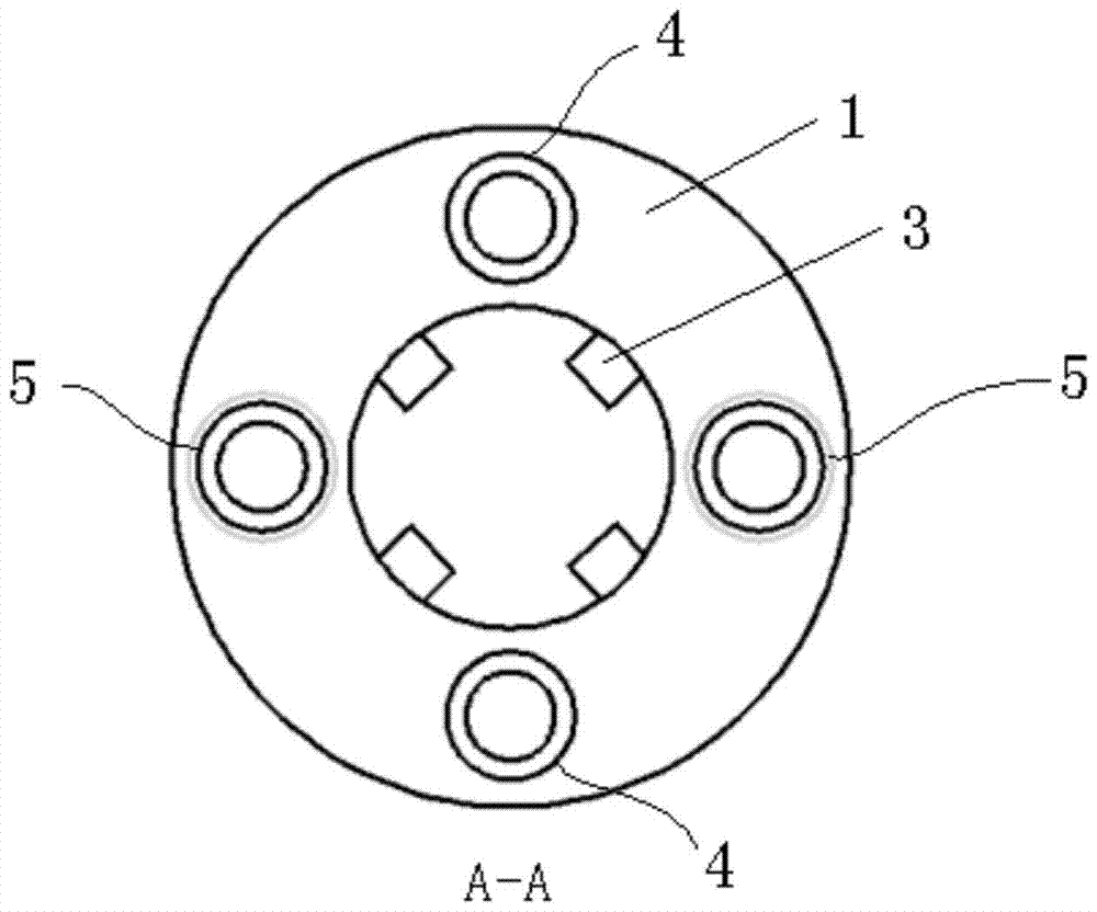
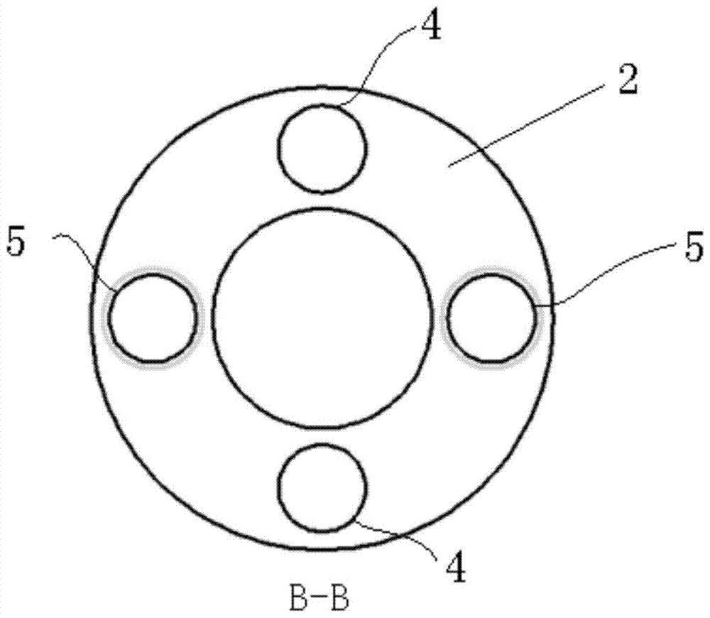
[0015] Such as Figure 1~3 As shown, the present invention proposes a spring-hydraulic type riser string suspension device, which includes an upper panel 1 and a lower panel 2 oppositely arranged up and down, and the upper panel 1 and the lower panel 2 are two annular structures with equal dimensions. A plurality of retractable pins 3 evenly distributed along its inner edge are arranged on the upper disk surface 1, and the pins 3 are controlled by a hydraulic or mechanical drive mechanism (not shown) arranged in the upper disk surface to protrude. Or retract. Two high-voltage uprights 4 and two normal uprights 5 are arranged between the upper panel 1 and the lower panel 2, and the high-voltage uprights 4 and the common uprights 5 are alternately arranged. The high pressure column 4 includes a hydraulic cylinder 41, the bottom of the hydraulic cylind...


PUM


Abstract

The invention relates to a spring-based hydraulic device and a method for suspending a riser string. The device comprises an upper disk of a cyclic structure, a lower disk of the same cyclic structure arranged oppositely to the upper disk, a plurality of telescopic pins evenly distributed along the inner edge of the upper disk, two or more than two high-pressure upright columns arranged between the upper disk and the lower disk, and two or more than two common upright columns arranged between the upper disk and the lower disk, wherein each high-pressure upright column comprises a hydraulic cylinder, the bottom end of the hydraulic cylinder is fastened to the top surface of the lower disk, a piston rod is inserted into the hydraulic cylinder, the top end of the piston rod is fastened to the bottom surface of the upper disk, and the upper and lower cavities of the hydraulic cylinder are full of a high-pressure liquid; each common upright column comprises an outer barrel, an inner barrel located inside the outer barrel, a piston arranged at the bottom end of the inner barrel, and a high-strength spring sleeving the outer barrel and the inner barrel, and wherein the bottom end of the outer barrel is fastened to the top surface of the lower disk, the top end of the inner barrel is fastened to the bottom surface of the upper disk, and the top end of the high-strength spring props against the bottom surface of the upper disk, while the bottom end of the high-strength spring props against the top surface of the lower disk.

Description

technical field [0001] The invention relates to a suspension device and a suspension method, in particular to a spring hydraulic type water riser string suspension device and a suspension method. Background technique [0002] Typhoons and other emergencies may be encountered during deepwater drilling and completion operations. At this time, for floating drilling platforms that are undergoing drilling and completion operations, it is necessary to initiate typhoon emergency measures, that is, stop deepwater drilling and completion operations and recover all drilling compartments. Hose, evacuate floating rig. In special cases, such as when the water depth is deep (more than 3000m), the recovery time of the riser may exceed 5 days. Before the typhoon comes, the wind force and trajectory in the next 4 to 5 days can generally be predicted through the weather forecast. Therefore, there may be no Time to fully recover the riser. Another example is some local typhoons or sudden typ...

Claims


Application Information

Patent Timeline
Patent Type & Authority Patents(China)
IPC IPC(8): E21B23/00
CPCE21B23/04
Inventor 许亮斌盛磊祥王荣耀蒋世全周建良李迅科张彦廷
Owner CHINA NAT OFFSHORE OIL CORP
Learn More