Supercharge Your Innovation With Domain-Expert AI Agents!

Suction duct with adjustable diametric fit

A suction pipe, compressor technology, applied in the field of compressors

Active Publication Date: 2015-01-28
BITZER KUEHLMASCHINENBAU GMBH
View PDF11 Cites 2 Cited by
  • Summary
  • Abstract
  • Description
  • Claims
  • Application Information

AI Technical Summary

Problems solved by technology

[0004] Some scroll compressors are known to have axial constraints such that the fixed scroll member has a limited range of movement

Method used


Image

  • Suction duct with adjustable diametric fit
  • Suction duct with adjustable diametric fit
  • Suction duct with adjustable diametric fit

Examples


Embodiment Construction

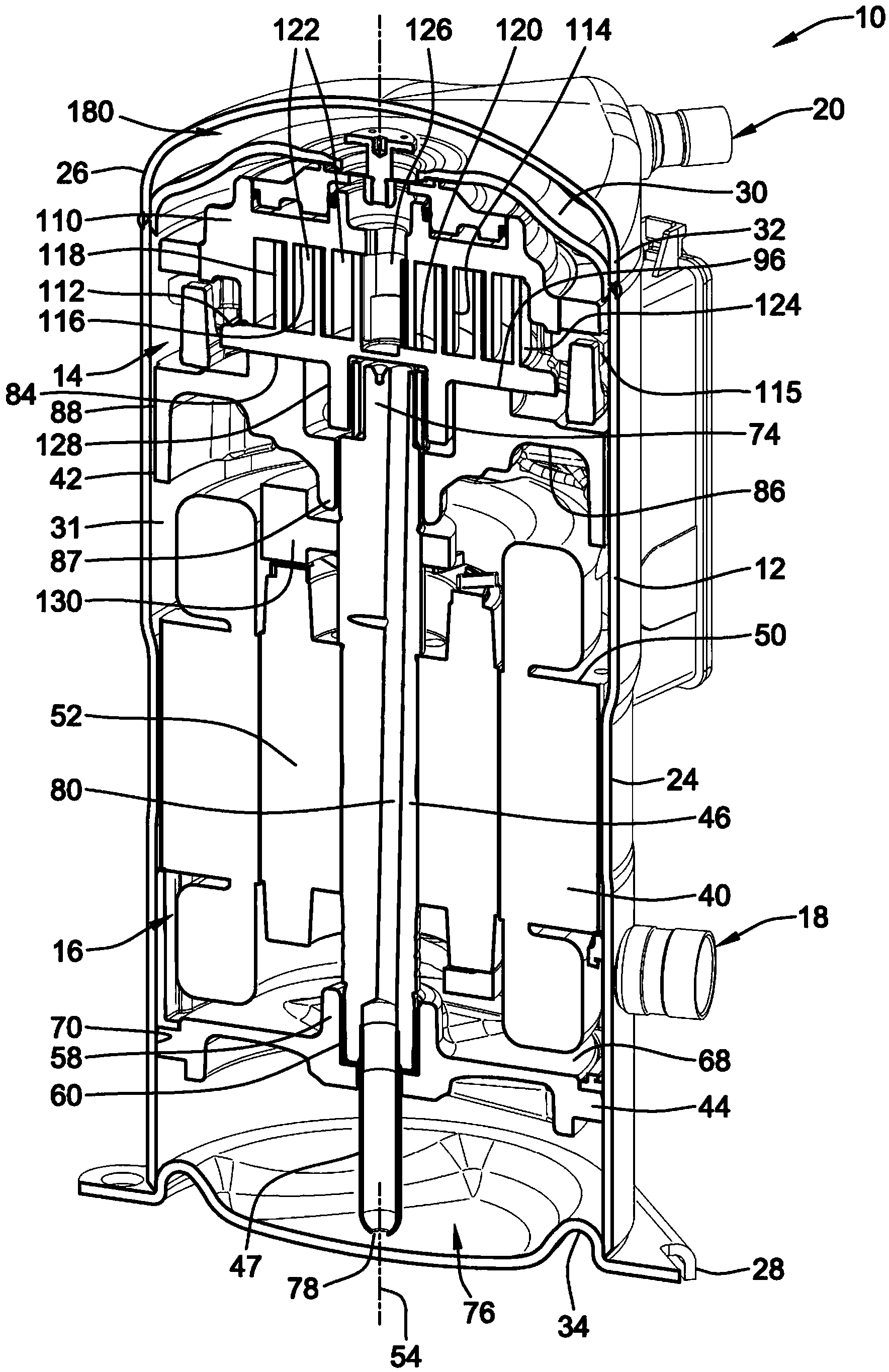
[0055] An embodiment of the invention is shown in the drawings as a scroll compressor assembly 10 generally comprising an outer housing 12 within which a scroll compressor 14 is drivable by a drive unit 16 . The scroll compressor assembly 10 may be provided in a refrigeration circuit for refrigeration, industrial cooling, freezing, air conditioning equipment, or other suitable equipment requiring compressed refrigerant. Suitable interfaces provide connection to the refrigeration circuit and include a refrigerant inlet 18 and a refrigerant outlet 20 extending through the outer shell 12 . The scroll compressor assembly 10 is operable by operation of the drive unit 16 to operate the scroll compressor 14 and thereby expel a suitable refrigerant that enters the refrigerant inlet 18 and is expelled from the refrigerant outlet 20 in a compressed, high pressure state. or other fluids to be compressed.

[0056] The outer casing of scroll compressor assembly 10 may take a variety of fo...


PUM


Abstract

A suction duct for a compressor such as a scroll compressor may include a plastic ring body with a metal screen heat staked in a window of the ring body to filter refrigerant gas entering the motor cavity. The ring body may be in surrounding relation of the motor and resiliently compressed in the housing through intermittent contact with the inner housing surface to better seal around the inlet port. Oil drain channels and stabilizing ribs may be along the outside surface of the ring body.

Description

technical field [0001] With some embodiments relating to scroll compressors, the present invention relates generally to a compressor for compressing refrigerant, and more particularly to an apparatus for filtering fluid prior to entering a compressor assembly. Background technique [0002] A scroll compressor is a specific type of compressor used to compress refrigerant for equipment such as refrigeration, air conditioning, industrial cooling and freezing equipment, and / or other equipment that uses compressed fluids. Such prior scroll compressors are known, for example, in US Patent 6,398,530 to Hasemann, US Patent 6,814,551 to Kammhoff et al., US Patent 6,960,070 to Kammhoff et al., and US Patent to Kammhoff et al. Yes, all of these patents are assigned to Bitzer entities closely related to this assignee. The entire disclosures of US Patent Documents 6,398,530, 7,112,046, 6,814,551, and 6,960,070 are hereby incorporated by reference in their entireties, as this disclosure ...

Claims


Application Information

Patent Timeline
IPC IPC(8): F04C18/02F04C29/02
CPCF04C23/008F04C29/12F04C27/008F01C21/10F04C29/0092F04C29/045F04C18/0215
Inventor R·J·杜普尔特T·罗加尔斯基
Owner BITZER KUEHLMASCHINENBAU GMBH
Features
  • R&D
  • Intellectual Property
  • Life Sciences
  • Materials
  • Tech Scout
  • Unparalleled Data Quality
  • Higher Quality Content
  • 60% Fewer Hallucinations
Learn More