
Straw compression molding equipment
A compression molding and equipment technology, applied in the direction of material molding presses, presses, manufacturing tools, etc., can solve the problems of frequent shutdown, small output, high labor intensity, etc., to increase frictional shear force, reasonable proportion matching, The effect of convenient replacement and maintenance
- Summary
- Abstract
- Description
- Claims
- Application Information
AI Technical Summary
Problems solved by technology
Method used
Image

Examples
Embodiment Construction
[0020] The present invention will be described in further detail below in conjunction with the accompanying drawings.
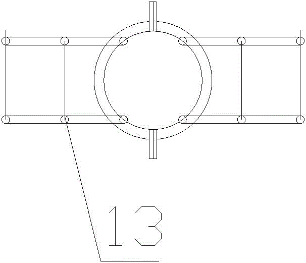
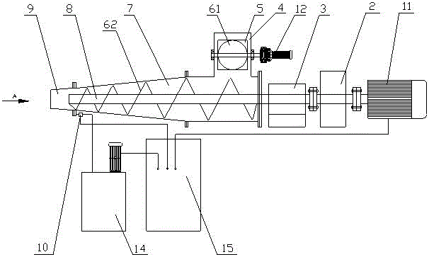
[0021] A kind of straw compression molding equipment of the present invention comprises a main drive mechanism, a pre-compression mechanism and a compression mechanism, the main drive mechanism includes a first motor 11, a reducer 2 and a bearing sleeve 3, the first motor 11, a reducer 2 Connected with the bearing sleeve 3 through the compression main shaft 8 in turn, the pre-compression mechanism includes the second motor 12, the feed box 4, the pre-compression auger 61 and the forced feeding flap 5, and the forced feeding flap 5 is arranged on Below the pre-compression auger 61, the compression mechanism includes a compression chamber 7, the compression main shaft 8 and a compression auger 62 centered on the compression main shaft 8, and the outlet end of the compression chamber 7 is provided with a reinforced compression chamber 9, The side wall of the rei...
PUM
 Abstract
Description
Claims
Application Information