
Spliced mutton detection device and detection method
A detection device and a technology for splicing mutton, which are applied in the measurement of color/spectral characteristics, etc., can solve the problems of low precision and long time consumption, and achieve the effects of high reliability and precision, improved reliability, and wide detection range.
- Summary
- Abstract
- Description
- Claims
- Application Information
AI Technical Summary
Problems solved by technology
Method used
Image

Examples
Embodiment 1
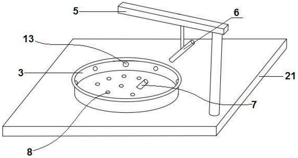
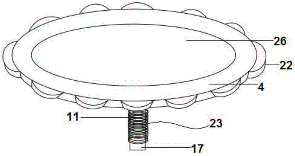
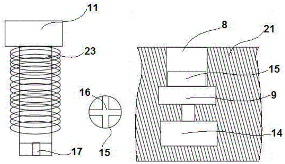
[0069] Such as figure 1 , figure 2 , image 3 , Figure 4 The illustrated embodiment is a splicing mutton detection device, including a light-tight housing, a laser array 20 composed of 6 lasers that can emit lasers of different wavelengths, and a spectrometer 1, such as figure 1 As shown, the container 3 and the support 5 with the upper opening in the housing, the circular sample tray 4 located in the container, and the light emitting head 6 provided on the support for irradiating light to the sample are located on the bottom plate of the container. A light-receiving head 7 for receiving transmitted light; the sample tray is provided with a light-transmitting plate 26 for placing samples, and the height of the upper end of the light-receiving head is lower than the height of the lower surface of the sample tray; the light-transmitting plate is made of quartz glass material .
[0070] Such as Figure 4 As shown, the laser array and the light emitting head are electricall...
Embodiment 2
[0110] In embodiment 2, such as figure 1 As shown, the container is provided with an electric telescopic rod 25, the upper part of the electric telescopic rod is connected with the light receiving head, and the electric telescopic rod is provided with a signal interface for electrical connection with a computer. Such as Figure 4 As shown, the light intensity adjusting device includes an N1-6259 data acquisition card 18 and a power amplifier 19, the data acquisition card is provided with a signal input interface for electrical connection with a computer, the data acquisition card is electrically connected to the input end of the power amplifier, and the power amplifier The output terminal is electrically connected with the power supply of the laser array.
[0111] Also include the following steps:
[0112] The computer adjusts the detection light output by the laser array through the light intensity adjustment device. The detection light rises from 0 to the maximum value MAT...
PUM
| Property | Measurement | Unit |
|---|---|---|
| Thickness | aaaaa | aaaaa |
| Angle of incidence | aaaaa | aaaaa |
Abstract
Description
Claims
Application Information