Sealed Claw Pole Axial Magnetic Permanent Magnet Brushless DC Motor

A DC motor and axial magnetic circuit technology, applied in the direction of magnetic circuit rotating parts, magnetic circuits, electric components, etc., can solve the problem that the brush motor cannot meet the high life requirements of the engine, the difficulty of layout, the complexity of quality control, and the unfavorable system integration and other problems, to achieve the effect of reducing the probability of corrosion failure, large torque, and broad market prospects

CN104377843BInactive Publication Date: 2017-05-17SUZHOU FUGENA ELECTROMECHANICAL CO LTD
4 Cites 2 Cited by

Patent Information

Authority / Receiving Office
CN · China
Patent Type
Patents(China)
Current Assignee / Owner
Publication Date
2017-05-17
Estimated Expiration
Not applicable · inactive patent

Smart Images

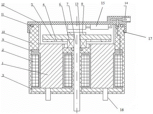
  • Figure 1
    Figure 1
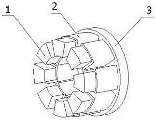
  • Figure 2
    Figure 2
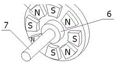
  • Figure 3
    Figure 3
Patent Text Reader

Abstract

The invention provides a sealing claw pole and axial magnetic circuit permanent magnetic brushless direct-current motor. A motor stator is characterized in that claw poles are uniformly and perpendicularly fixed around a base, central lines of the claw poles are parallel to axis of a rotating shaft, a coil winding is mounted on each claw pole in a sleeved manner, the base of the motor stator and the coil windings on the claw poles of the base are covered and sealed by plastic to form a barrel-shaped plastic sealing member, and a cover covers and seals the barrel-shaped plastic sealing member; the rotating shaft of a motor rotor penetrates the stator base, an iron core is perpendicularly fixed, permanent magnet magnetic steel is uniformly fixed on the iron core, and sensor magnetic steel is fixed at the center of the other side of the iron core and corresponds to a Hall sensor fixed on the inner wall of the cover. The sealing claw pole and axial magnetic circuit permanent magnetic brushless direct-current motor has the advantages that an axial magnetic circuit is adopted, and the motor is large in torque, high in efficiency, small in size and space and high in system integrity.
Need to check novelty before this filing date? Find Prior Art

Description

technical field

[0001] The present invention relates to electric motors for automotive engine applications, such as control of valves for throttle, waste recirculation, turbocharging, swirl control, etc. Background technique

[0002] With the improvement of the national economy and people's living standards, the number of various vehicles is increasing rapidly year by year, and the electrification of automobile engine control is constantly advancing, replacing the original simple mechanical or hydraulic control. The precise control of electrification can greatly improve the performance of the car, reduce fuel consumption, and control emissions at the same time. The electrification control of these valve bodies requires precision electromechanical products to implement control, and this motor must be able to withstand the high temperature, vibration, and erosion of the engine environment, while ensuring long service life.

[0003] The electronic components inside the motor a...

Examples

Embodiment Construction

[0022] Please refer to the accompanying drawings, the stator of the motor of the present invention is vertically and uniformly fixed claw poles 1 around a base 3, the center line of the claw poles 1 is parallel to the axis of the rotating shaft 7, and the coil winding 2 is placed on the claw poles 1. The base of the motor stator 3. The coil winding 2 on the claw pole 1 of the base is covered with plastic material 10 to form a barrel-shaped plastic seal, and a cover 12 is sealed on the barrel-shaped plastic seal. The rotating shaft 7 of the motor rotor passes through the stator base 3, Fix an iron core 5 vertically, fix the permanent magnet magnetic steel 4 evenly on the iron core 5, and fix a sensor magnetic steel 8 at the center of the other surface of the iron core 5. Corresponding to the sensor 15, the sensor used in the present invention has no PCB board structure, and the Hall sensor is packaged in one piece, which avoids the risk of failure of common PCB board electronic ...