
Adaptive precoding based on channel state information reliability

A technology of channel state information and precoding vectors, which is applied in the field of spatial precoding, and can solve problems such as the occasional problem of unreliable precoder information for a single mobile terminal

Active Publication Date: 2015-03-04
TELEFON AB LM ERICSSON (PUBL)
View PDF5 Cites 30 Cited by
  • Summary
  • Abstract
  • Description
  • Claims
  • Application Information

AI Technical Summary

Problems solved by technology

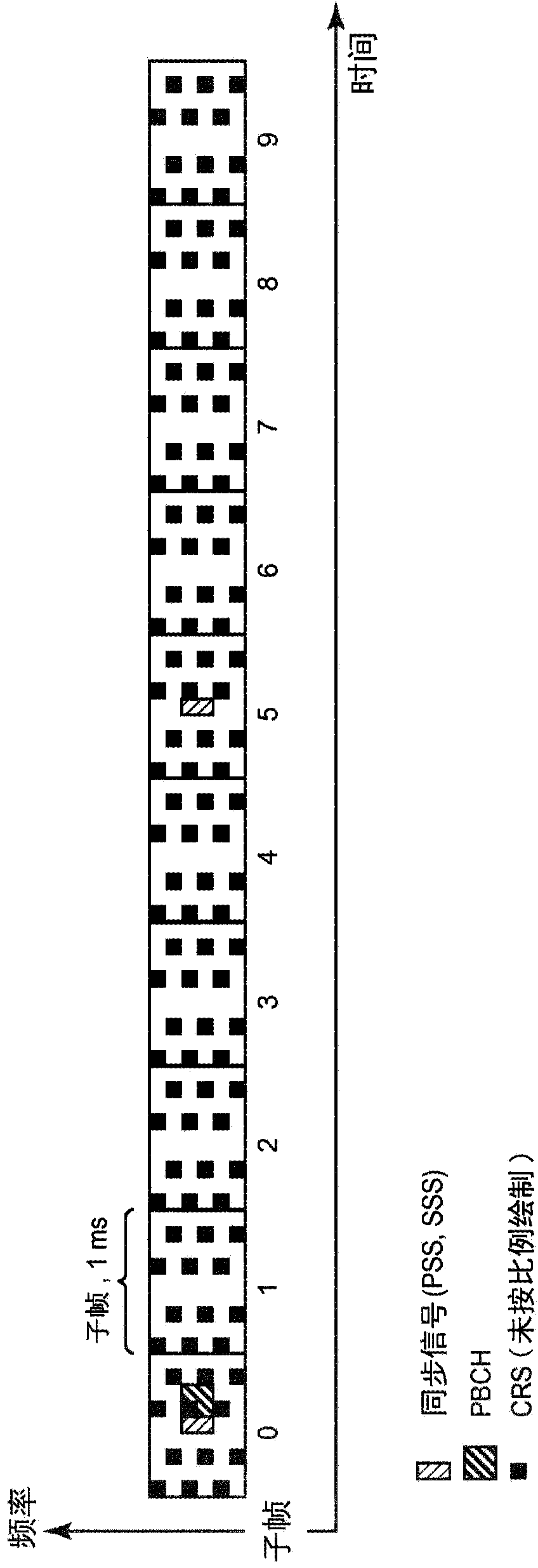
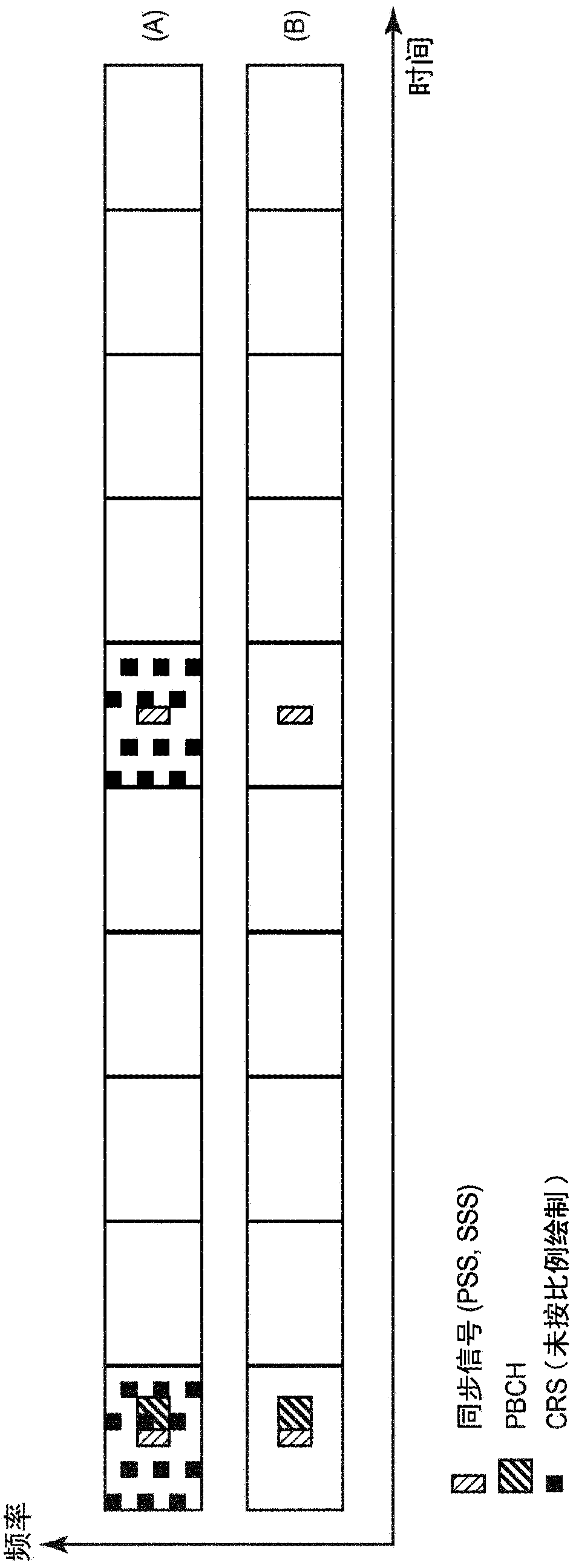
Clearly, enabling CRS is not an energy-efficient solution to the occasional problem of unreliable or non-existent precoder information for a single mobile terminal

Method used


Image

  • Adaptive precoding based on channel state information reliability
  • Adaptive precoding based on channel state information reliability
  • Adaptive precoding based on channel state information reliability

Examples


Embodiment Construction

[0029] The invention is described more fully hereinafter with reference to the accompanying drawings, in which examples of embodiments of the invention are shown. This invention may, however, be embodied in different forms and should not be construed as limited to the embodiments set forth herein. It should also be noted that these embodiments are not mutually exclusive. Thus, it may be assumed that a component or feature from one embodiment is present in or used in another embodiment where such inclusion is appropriate.

[0030] For purposes of illustration and explanation only, the present invention is described herein in the context of operating in a radio access network (RAN) communicating with wireless terminals (also referred to as user equipment or "UE") over wireless communication channels These and other examples of . More specifically, it is described in the context of systems using the Long Term Evolution (LTE) technology, also known as the Evolved UMTS Terrestria...


PUM


Abstract

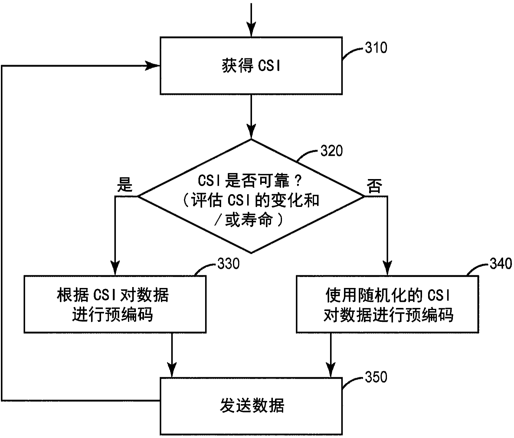
In a system using spatial precoding, in the event that reliable channel state information is unavailable, a transmitting node artificially creates a randomization of the precoders applied to the transmitted signal. Different precoding vectors are applied to both transmitted data and demodulation reference signals for each of several groups of time-frequency resources, where the precoding vectors vary randomly or pseudo-randomly from each group of time-frequency resources to the next frequency-adjacent group or groups, or to the next time-adjacent group or groups, or both. In an LTE system in particular, this randomization of precoders can be applied at the resource-block level or, at the level of the Precoding Resource block Group (PRG), for example. Thus, the precoders applied to the transmitted signal vary from one PRG to the next, in a random or pseudo-random fashion.

Description

technical field [0001] The present invention relates generally to wireless communication systems and, more particularly, to techniques for spatially precoding signals transmitted from multiple antennas. Background technique [0002] In many wireless communication systems, wireless receivers use one or more of various types of pilot signals to assist in demodulating received signals. These pilot signals are often referred to as reference signals and / or reference symbols. In the 3rd Generation Partnership Project (3GPP) specification for the Long Term Evolution (LTE) wireless system (also commonly referred to as the Evolved UMTS Terrestrial Radio Access Network or E-UTRAN), the receiving wireless device has two different There are two frequency signal types used for data demodulation, namely, Common Reference Signal (CRS) and Demodulation Reference Signal (DMRS). In 3GPP specifications, for example, in Evolved Universal Terrestrial Radio Access (E-UTRA); Physical channels an...

Claims


Application Information

Patent Timeline
IPC IPC(8): H04L25/02H04L25/03H04L5/00
CPCH04B7/0417H04B7/0656H04L25/03343H04L5/0051H04L5/0023H04L25/0222H04L25/03949
Inventor 本特·林多夫弗雷德里克·努德斯特伦
Owner TELEFON AB LM ERICSSON (PUBL)
Learn More