
Coding of a syntax element contained in a pre-coded video signal

a video signal and syntax element technology, applied in the field of video signal coding of syntax elements contained in pre-coded video signals, can solve the problems of not being able to adapt to actual symbol statistics, the set of fixed vlc tables cannot be used to exploit existing inter-symbol redundancies within these coding schemes, and the high-order statistical dependencies on a syntax element level are mostly neglected in existing video coding schemes. achieve better approximation, improve compression ratio, and enhance compression ratio

Active Publication Date: 2007-10-23
FRAUNHOFER GESELLSCHAFT ZUR FOERDERUNG DER ANGEWANDTEN FORSCHUNG EV
View PDF10 Cites 119 Cited by
  • Summary
  • Abstract
  • Description
  • Claims
  • Application Information

AI Technical Summary

Benefits of technology

The present invention provides a coding scheme for a pre-coded video signal that allows for more efficient compression. This is achieved by assigning a syntax element to one of at least two context models, based on the neighboring portions of the video frame being precoded in a first or second way. The probability estimation of each context model is adapted to the previously coded syntax elements, allowing for a more accurate estimation of the actual probability distribution. This results in a higher compression ratio of the coded bit stream to the pre-coded video signal.

Problems solved by technology

Moreover, higher-order statistical dependencies on a syntax element level are mostly neglected in existing video coding schemes.
The set of fixed VLC tables does not allow an adaptation to the actual symbol statistics, which may vary over space and time as well as for different source material and coding conditions.
Finally, since there is a fixed assignment of VLC tables and syntax elements, existing inter-symbol redundancies cannot be exploited within these coding schemes.

Method used


Image

  • Coding of a syntax element contained in a pre-coded video signal
  • Coding of a syntax element contained in a pre-coded video signal
  • Coding of a syntax element contained in a pre-coded video signal

Examples


Embodiment Construction

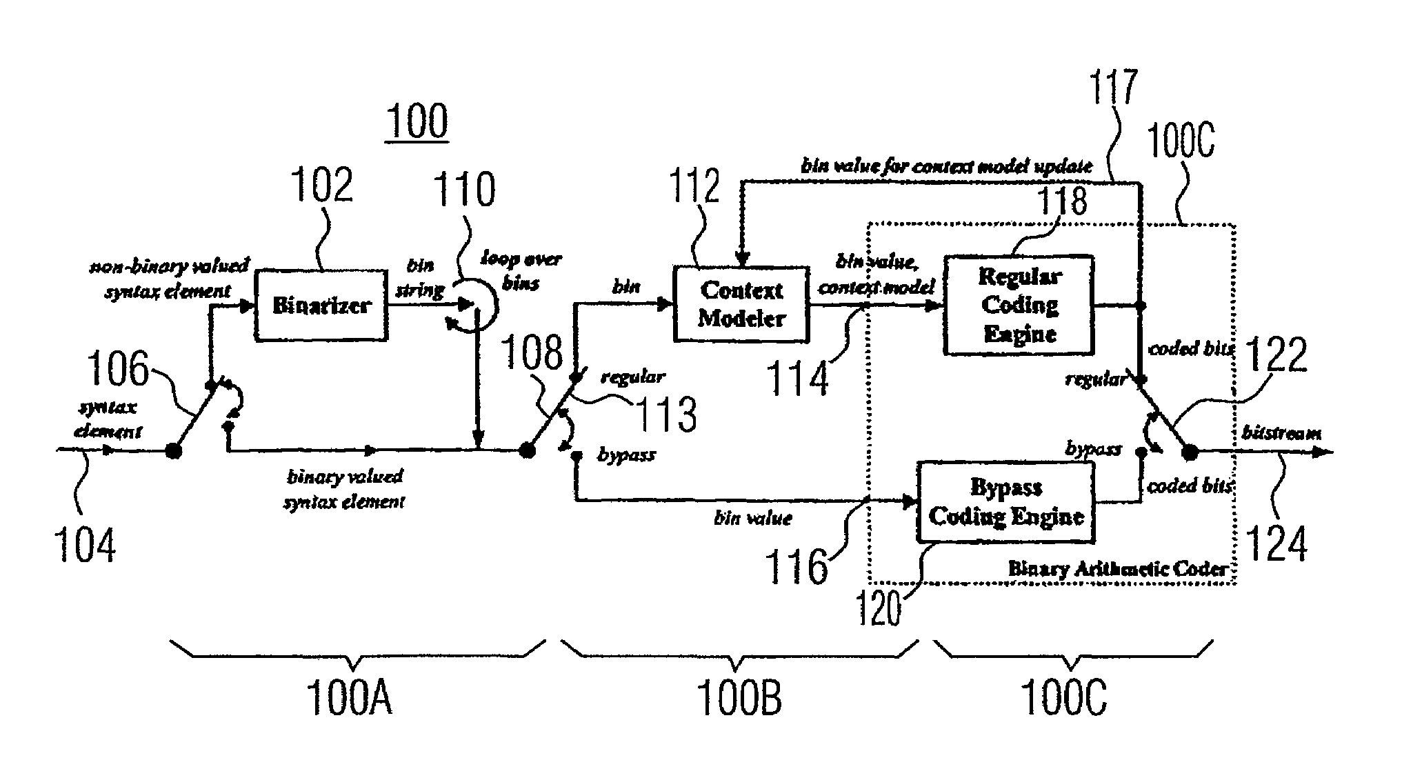
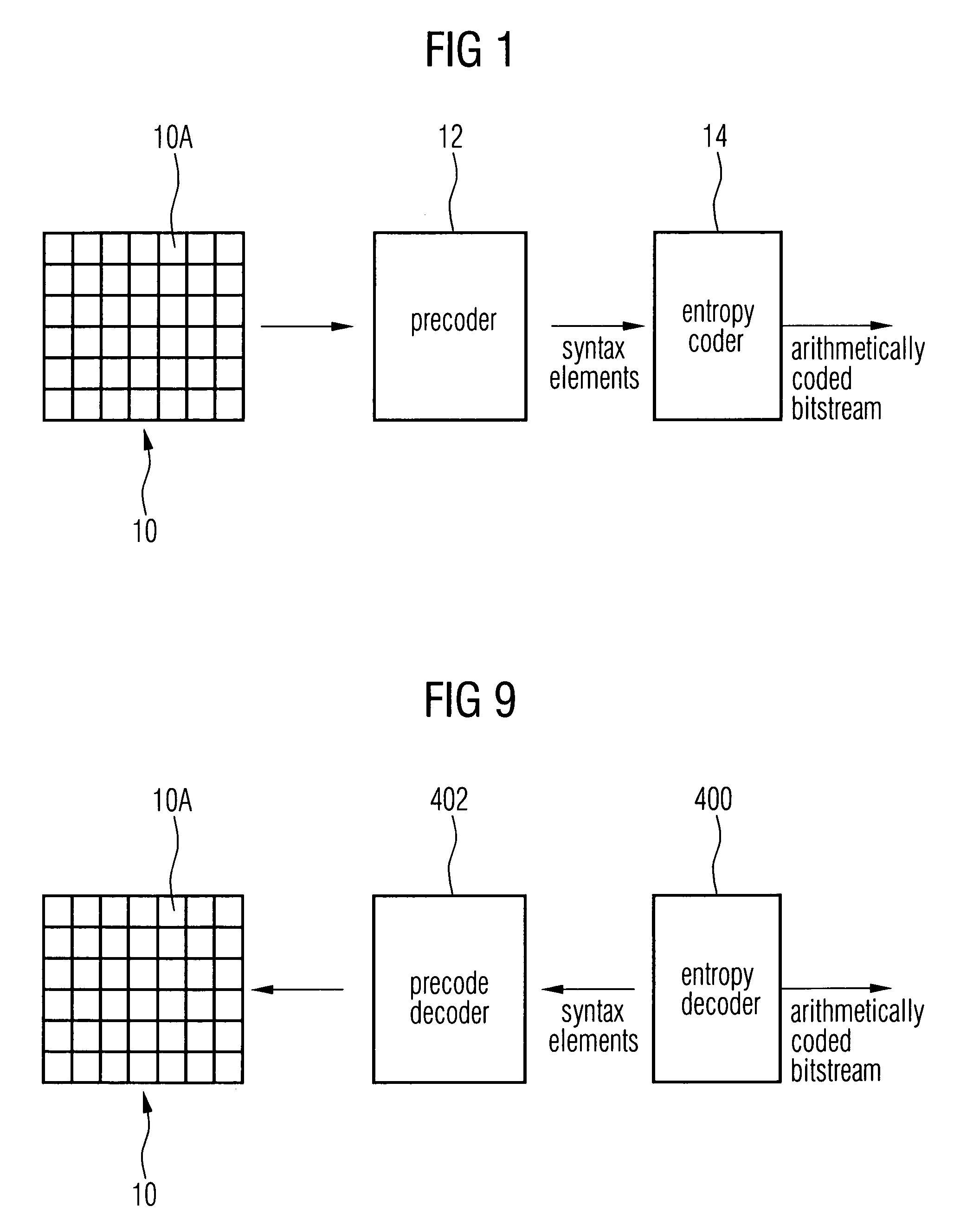
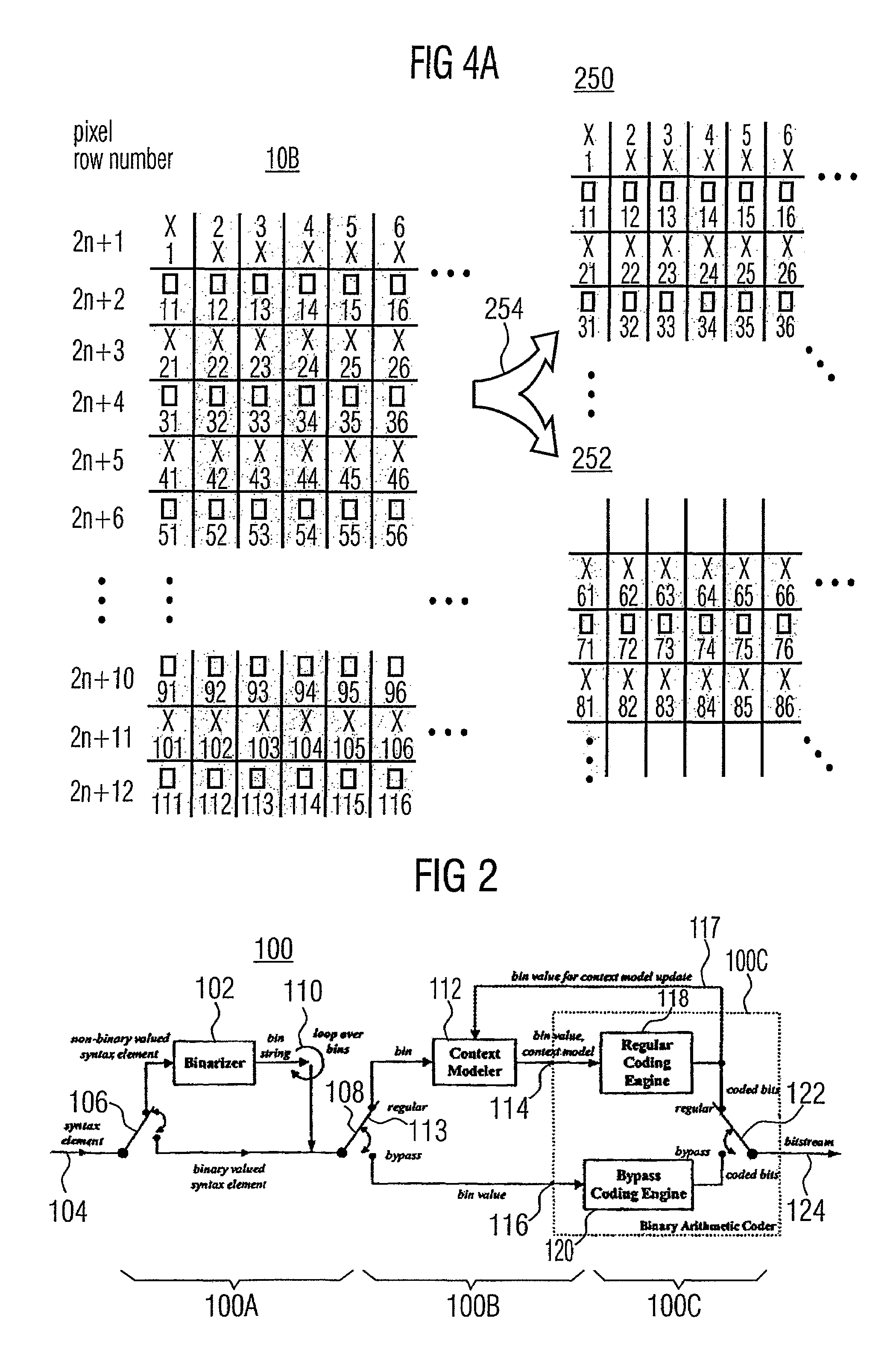
[0036]FIG. 1 shows a general view of a video encoder environment to which the present invention could be applied. A picture of video frame 10 is fed to a video precoder 12. The video precoder treats the picture 10 in units of so-called macroblocks 10a. Each macroblock contains several picture samples of picture 10. On each macroblock a transformation into transformation coefficients is performed followed by a quantization into transform coefficient levels. Moreover, intra-frame prediction or motion compensation is used in order not to perform the afore mentioned steps directly on the pixel data but on the differences of same to predicted pixel values, thereby achieving small values which are more easily compressed.

[0037]Precoder 12 outputs the result, i.e., the precoded video signal. All residual data elements in the precoded video signal, which are related to the coding of transform coefficients, such as the transform coefficient levels or a significance map indicating transform co...


PUM


Abstract

A method for encoding a syntax element contained in a precoded video signal into a coded bit stream, the precoded video signal representing at least one video frame, the syntax element being associated with a predetermined portion of the video frame and being indicative of as to whether the predetermined portion of the video frame is precoded in a first or a second way into the precoded video signal is described. The method comprises investigating as to whether a neighboring portion of the video frame neighboring the predetermined portion is precoded in the first way or the second way, in order to obtain a binary value; assigning one of at least two context models to the predetermined portion of the video frame based on the binary value, wherein each context model is associated with a different probability estimation; and arithmetically encoding the syntax element into the coded bit stream based on the probability estimation with which the assigned context model is associated.

Description

BACKGROUND OF THE INVENTION[0001]I. Technical Field of the Invention[0002]The present invention is related to coding of syntax elements contained in a pre-coded video signal into a coded bit stream and, in particular, to an arithmetic coding scheme for such syntax elements.[0003]II. Description of the Prior Art[0004]Entropy coders map an input bit stream of binarizations of data values to an output bit stream, the output bit stream being compressed relative to the input bit stream, i.e., consisting of less bits than the input bit stream. This data compression is achieved by exploiting the redundancy in the information contained in the input bit stream.[0005]Entropy coding is used in video coding applications. Natural camera-view video signals show non-stationary statistical behavior. The statistics of these signals largely depend on the video content and the acquisition process. Traditional concepts of video coding that rely on mapping from the video signal to a bit stream of variab...

Claims


Application Information

Patent Timeline
Patent Type & Authority Patents(United States)
IPC IPC(8): G06K9/46G06K9/36H03M7/00H03M7/34H04N7/26
CPCH04N19/196H04N19/16H04N19/463H04N19/13
Inventor MARPE, DETLEVSCHWARZ, HEIKOWIEGAND, THOMAS
Owner FRAUNHOFER GESELLSCHAFT ZUR FOERDERUNG DER ANGEWANDTEN FORSCHUNG EV
Learn More