
Suspension components on outer ring measuring devices for automatic ball bearing assembly machines

A technology for suspension components, measuring devices, used in bearing elements, mechanical bearing testing, shafts and bearings, etc.

Inactive Publication Date: 2017-01-18
HEILONGJIANG UNIV
View PDF6 Cites 0 Cited by
  • Summary
  • Abstract
  • Description
  • Claims
  • Application Information

AI Technical Summary

Problems solved by technology

[0003] The purpose of the present invention is to solve the problem that the outer ring measuring device of the ball bearing automatic assembly machine needs to have a supporting suspension part, and to provide a suspension part for the outer ring measuring device of the ball bearing automatic assembly machine

Method used


Image

  • Suspension components on outer ring measuring devices for automatic ball bearing assembly machines
  • Suspension components on outer ring measuring devices for automatic ball bearing assembly machines
  • Suspension components on outer ring measuring devices for automatic ball bearing assembly machines

Examples


specific Embodiment approach 1

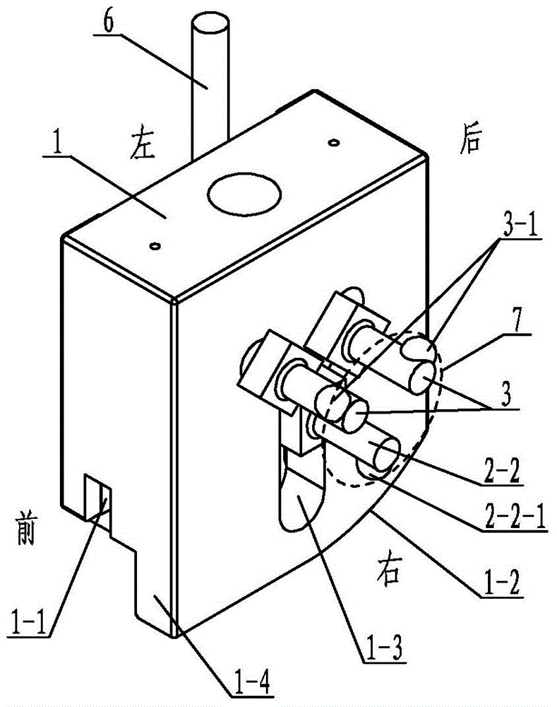
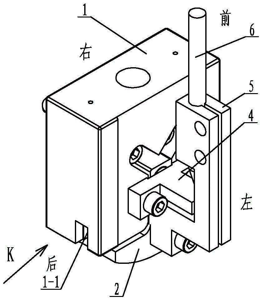
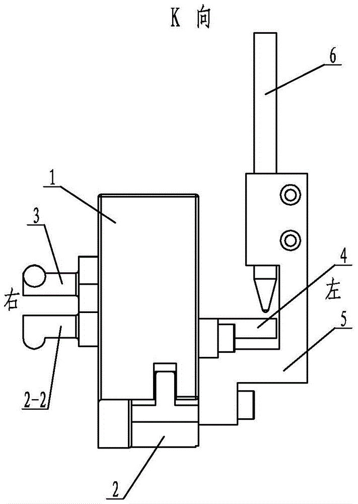
[0012] Embodiment 1: Combining Figure 1 to Figure 3 Illustrating this embodiment, this embodiment includes a main measuring body 1, a moving measuring body 2, a measuring fixed block 4, a measuring moving block 5, an outer ring measuring sensor 6 and two fixed support rods 3. The moving measuring body 2 is formed by the moving measuring body. The seat 2-1, the movable support rod 2-2, the two measuring columns 2-3 and the two compression springs 2-4 are composed. The middle part of the movable measuring body seat 2-1 is provided with a mounting seat 2-1-1. The upper end surface of 2-1-1 is provided with a long groove 2-1-2 for the movable measuring support rod, and the movable measuring body seat 2-1 is provided with mounting ribs 2-1 on both sides of the mounting seat 2-1-1. 1-3, a measuring column 2-3 is fixed on each mounting rib 2-1-3, a compression spring 2-4 is set on the upper end of each measuring column 2-3, and the movable support rod 2-2 is set on the movable measu...

specific Embodiment approach 2

[0013] Specific implementation mode 2: Combining figure 1 Describing this embodiment, the two inclined grooves on the Y-shaped through grooves 1-3 in this embodiment are symmetrically arranged relative to the vertical grooves. In this way, the fixed support rod 3 and the movable support rod 2-2 are evenly distributed along the circumference, and the contact between the two spherical fixed measuring fulcrums 3-1 and one dynamic measuring fulcrum 2-2-1 in the inner diameter of the outer ring T of the bearing under test is ensured. The points are evenly distributed, so that the measured value of the T dimension of the bearing outer ring is more accurate. Other components and connection relationships are the same as in the first embodiment.

specific Embodiment approach 3

[0014] Specific implementation three: combination figure 1 Illustrating this embodiment, the included angle between the two inclined grooves on the Y-shaped through grooves 1-3 in this embodiment is less than or equal to 90°. In this way, the fixed support rod 3 and the movable support rod 2-2 are evenly distributed along the circumference, and the contact between the two spherical fixed measuring fulcrums 3-1 and one dynamic measuring fulcrum 2-2-1 in the inner diameter of the outer ring T of the bearing under test is ensured. The points are evenly distributed, so that the measured value of the T dimension of the bearing outer ring is more accurate. Other compositions and connection relationships are the same as in the first or second embodiment.


PUM


Abstract

The invention discloses a suspension part on an outer ring measuring device of a ball bearing automatic assembly machine. An installation base on a movable measuring body and an installation rib are arranged in a movable measuring body installation slot, a measuring cylinder is arranged in each guide hole, a movable measuring pivot point on a movable supporting rod is a ball body, one end of the movable supporting rod is exposed to the right end of a main measuring body, a vertical slot of a Y-shaped through slot is opposite to a long slot of the movable measuring supporting rod, a fixed supporting rod is arranged in each of two inclined slots in the Y-shaped through slot, a spherical fixed measuring point is arranged at the outer side of each fixed supporting rod, a measuring fixed block is arranged on the left end surface of the main measuring body, the upper end surface of the measuring fixed block is positioned below the two inclined slots of the Y-shaped through slot, the measuring fixed block is fixedly connected to the main measuring body, a contact of an outer ring measuring sensor is positioned on the upper end surface of the measuring fixed block, the outer ring measuring sensor is arranged in a measuring movable block, and the measuring movable block is fixedly connected to a movable measuring body. The suspension part is used on the outer ring measuring device of the ball bearing automatic assembly machine.

Description

technical field [0001] The invention relates to a measuring device, in particular to a suspension part used for an outer ring measuring device of a ball bearing automatic assembly machine. Background technique [0002] When the ball bearing is fitted with a matching sleeve (matching), it needs to be carried out according to the requirements of the inner sleeve groove size, the outer sleeve groove size, the size of the ball ball, the clearance between the ball ball and the inner sleeve, the outer sleeve (oil gap), and the grade of the bearing. Therefore, the precision and speed of the size sorting of the inner and outer grooves of the ball bearing are very important. The existing ball bearing inner and outer casings are sorted and assembled manually, and the speed of sorting and assembling is slow, the quality of the inner and outer casings of the sorted bearings is difficult to guarantee, and the accuracy is poor. The ball bearing inner and outer ring sorting and matching m...

Claims


Application Information

Patent Timeline
Patent Type & Authority Patents(China)
IPC IPC(8): F16C43/04G01M13/04
Inventor 刘贺滨刘英涛杨联泳王姗姗张庆庆
Owner HEILONGJIANG UNIV
Learn More