Measuring components on an inner ring measuring device for an automatic ball bearing assembly machine
A technique for measuring components, measuring devices, applied in the direction of measuring devices, bearing elements, shafts and bearings
- Summary
- Abstract
- Description
- Claims
- Application Information
AI Technical Summary
Problems solved by technology
Method used
Image
Examples
specific Embodiment approach 1
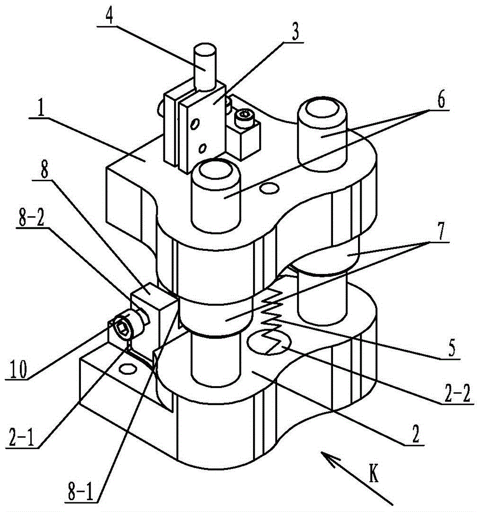
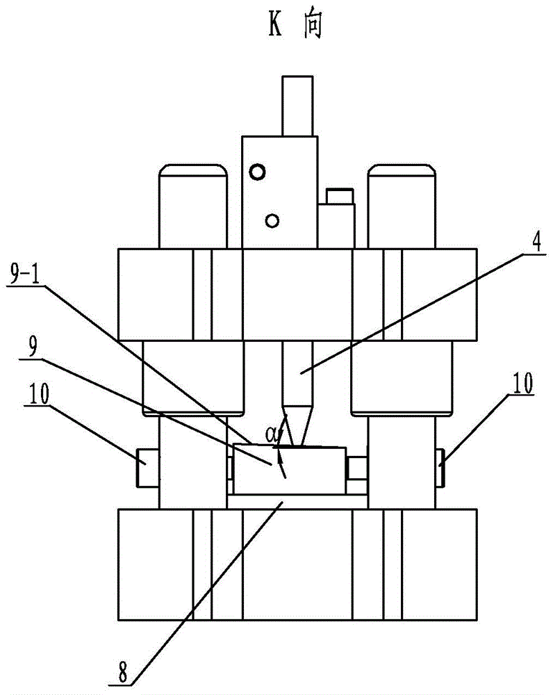
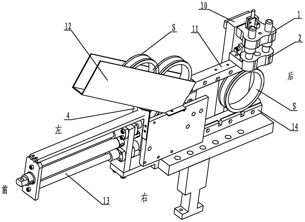
[0011] Specific implementation mode one: combine figure 1 and figure 2 Describe this embodiment, this embodiment includes inner ring fixed measuring part 1, inner ring moving measuring part 2, sensor frame 3, inner ring measuring sensor 4, first pressure spring 5, two measuring guide posts 6, two measuring guides Set 7, fine-tuning fixed body 8, fine-tuning block 9 and two fine-tuning screws 10, the inner ring fixed measuring part 1 and the inner ring moving measuring part 2 are set up and down in parallel, the measuring guide sleeve 7 is set on the measuring guide post 6, and the measuring The guide sleeve 7 is located between the inner ring measuring part 1 and the inner ring moving measuring part 2, and the upper end of the measuring guide post 6 passes through the inner ring fixing measuring part 1, and the lower end of the measuring guide post 6 is set on the inner ring moving measuring part 2 Among them, the measuring guide sleeve 7 is fixedly connected with the inner ...
specific Embodiment approach 2
[0012] Specific implementation mode two: combination figure 1 To illustrate this embodiment, the upper end surface of the inner ring moving measuring piece 2 of this embodiment is provided with a pressure spring lower hole 2-2, and the lower end surface of the inner ring fixed measuring piece 1 is provided with a pressure spring lower hole 2-2. Pair the hole on the pressure spring. The upper end of the first pressure spring 5 is fixed in the upper hole of the pressure spring, and the lower end of the first pressure spring 5 is fixed in the lower hole 2-2 of the pressure spring, which not only increases the compression length of the first pressure spring 5, but also makes the first The pressure spring 5 is connected more firmly. Other components and connections are the same as those in the first embodiment.
specific Embodiment approach 3
[0013] Specific implementation mode three: combination figure 2 The present embodiment will be described. The slope angle α of the inclined surface 9-1 in the present embodiment is 1° to 10°. The inclination angle α is within the above numerical range, so that the value of the bearing inner ring S measured by the sensor 4 is more accurate. Other compositions and connections are the same as those in Embodiment 1 or 2.
PUM
 Abstract
Description
Claims
Application Information
 - R&D
- Intellectual Property
- Life Sciences
- Materials
- Tech Scout
- Unparalleled Data Quality
- Higher Quality Content
- 60% Fewer Hallucinations
Browse by: Latest US Patents, China's latest patents, Technical Efficacy Thesaurus, Application Domain, Technology Topic, Popular Technical Reports.
© 2025 PatSnap. All rights reserved.Legal|Privacy policy|Modern Slavery Act Transparency Statement|Sitemap|About US| Contact US: help@patsnap.com


