Eureka AIR delivers breakthrough ideas for toughest innovation challenges, trusted by R&D personnel around the world.

An electrical lock zero device

A technology for locking zero and electric appliances, which is applied in the direction of circuits, electric switches, electrical components, etc. It can solve the problems of complicated locks and unsightly appearance of the device, and achieve the effects of convenient and reliable use, ensuring safe use, and simple structure of the device

Active Publication Date: 2017-11-03
温州合邦电气有限公司
View PDF9 Cites 0 Cited by
  • Summary
  • Abstract
  • Description
  • Claims
  • Application Information

AI Technical Summary

Problems solved by technology

[0002] The national standard stipulates that in order to ensure absolute safety in use, isolating switch electrical products must not only have an automatic zero-lock device for electrical products, but also a mechanical zero-lock device. The traditional mechanical zero-lock device is generally equipped with a padlock. Manually lock the padlock on the electrical product, this kind of device is more complicated and the appearance is not beautiful

Method used


Image

  • An electrical lock zero device
  • An electrical lock zero device
  • An electrical lock zero device

Examples


Embodiment Construction

[0017] combine Figure 1 to Figure 8 , the present invention will be further described through specific examples.

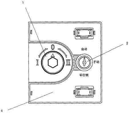
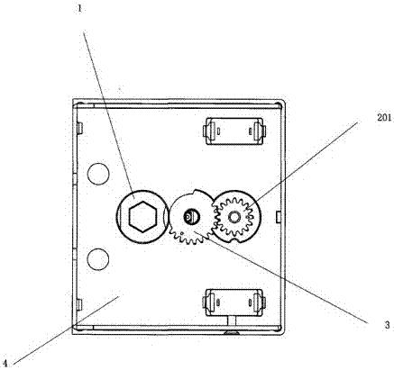
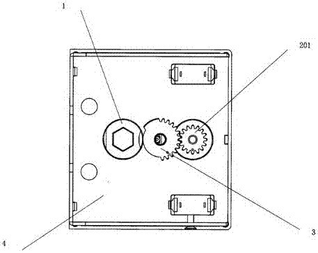
[0018] An electric appliance lock zero device is characterized in that: it comprises a mounting plate 4, a position adjustment lock 2 arranged on the right side of the installation plate 4, a handle wheel 1 arranged on the left side of the 1 between transmission wheels 3 .

[0019] Further setting, the transmission wheel 3 is set as a gear area 301, an action area 303 and a zero-lock area 302, the gear area 301 is provided with a transmission tooth 3010, and the action area 303 is one with the transmission tooth 3010 is an arc with the same radius as the dedendum circle, and the zero-lock zone 302 is an arc boss with the same radius as the addendum circle of the transmission tooth 3010.

[0020] Further set, described position adjustment lock 2 is set to automatic, manual and three kinds of working conditions of zero position lock, and position adjustment lock ...


PUM


Abstract

An electric appliance zero lock device comprises a mounting plate, a position adjusting lock arranged on the right side of the mounting plate, a handle wheel arranged on the left side of the mounting plate and a transmission wheel arranged between the position adjusting lock and the handle wheel. Due to the fact that the handle wheel, the position adjusting lock and the transmission wheel between the handle wheel and the position adjusting lock are adopted by the zero lock device, when the position adjusting lock is in an automatic or a manual state, an electric appliance product can run normally under and automatic or manual situation, when the handle wheel and the position adjusting lock are in the situation that a zero position is locked, no auxiliary equipment needs to be added, mechanical zero lock can be carried out on electric appliances conveniently, it is guaranteed that the electric appliances and loads are powered off under the condition that the zero position is locked, the using safety of the electric appliances is guaranteed, and the device is simple in structure and convenient and reliable to use.

Description

technical field [0001] The invention relates to a zero locking device for electrical products. Background technique [0002] The national standard stipulates that in order to ensure absolute safety in use, isolating switch electrical products must not only have an automatic zero-lock device for electrical products, but also a mechanical zero-lock device. The traditional mechanical zero-lock device is generally equipped with a padlock. Manually lock the padlock on the electrical appliance, this device is more cumbersome and not attractive in appearance. Contents of the invention [0003] The purpose of the present invention is to overcome the disadvantages of the traditional zero locking device, and disclose a zero locking device for electrical products. [0004] The technical solution adopted in the present invention is: an electric appliance lock zero device, including a mounting plate, a position adjustment lock arranged on the right side of the installation plate, a ha...

Claims


Application Information

Patent Timeline
Patent Type & Authority Patents(China)
IPC IPC(8): H01H9/20
CPCH01H9/20
Inventor 张韶松
Owner 温州合邦电气有限公司
Why Eureka
Eureka Blog
Learn More