
Metal powder preparation method and device based on controllable magnetic levitation smelting technology
A magnetic levitation smelting and metal powder technology, which is applied in the field of levitation smelting, can solve the problems that cannot meet the needs of industrial production, cannot stably control the flow rate of molten metal, and cannot avoid contact between metal materials and crucibles, and achieves convenient real-time measurement and monitoring, tensioning The effect of increasing the force and increasing the tension force
- Summary
- Abstract
- Description
- Claims
- Application Information
AI Technical Summary
Problems solved by technology
Method used
Image

Examples
Embodiment 1
[0051] A method for preparing metal powder based on controllable magnetic levitation smelting technology, comprising the following steps:
[0052] Step 1: Make one end of the metal wire pass through the electromagnetic field area at a constant speed.
[0053] Step 2: The metal wire heats up and melts in the electromagnetic field area, and continuously forms metal droplets.
[0054] Step 3: Metal droplets are continuously dripped into the gas atomization area.
[0055] Step 4: The high-pressure and high-speed inert gas breaks up the metal droplets in the gas atomization area.
[0056]Step 5: The metal droplets are broken up by the impact and cooled to form metal powder.
[0057] All the above steps are usually carried out under vacuum conditions, because usually metals can chemically react with certain components in the air, and the components change.
[0058] The above-mentioned method is suitable for the production of metal wire as the raw material, and it is easy to contr...
Embodiment 2
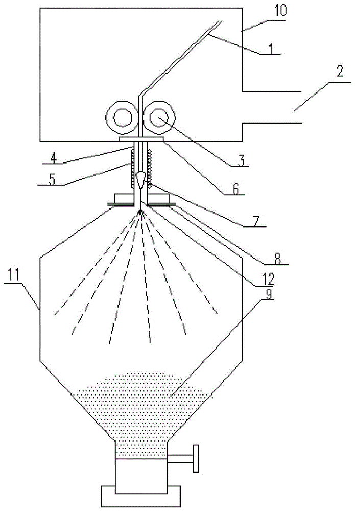
[0061] A metal powder preparation device based on controllable magnetic levitation smelting technology, such as figure 1 shown, including:
[0062] A vacuum chamber 10, the vacuum chamber 10 is provided with an air suction port 2 and a wire outlet 6, and the air suction port 2 is connected to a vacuum suction device;
[0063] A pair of rollers 3 arranged in the vacuum cavity 10, the axes of the two rollers 3 are parallel, the rotation directions of the two rollers 3 are opposite, and the gap between the rotating surfaces of the two rollers 3 is equal to the diameter of the wire 1 Matching; the gap between the rotating surfaces of the two rollers 3 communicates with the wire outlet;
[0064] A quartz glass tube 4 with openings at both ends, one end of the quartz glass tube 4 is connected to the wire outlet, and the other end is connected to the gas atomization nozzle 8 and the powder collector 11 in sequence;
[0065] The quartz glass tube 4 is wound with a coil 5 for molten ...
Embodiment 3
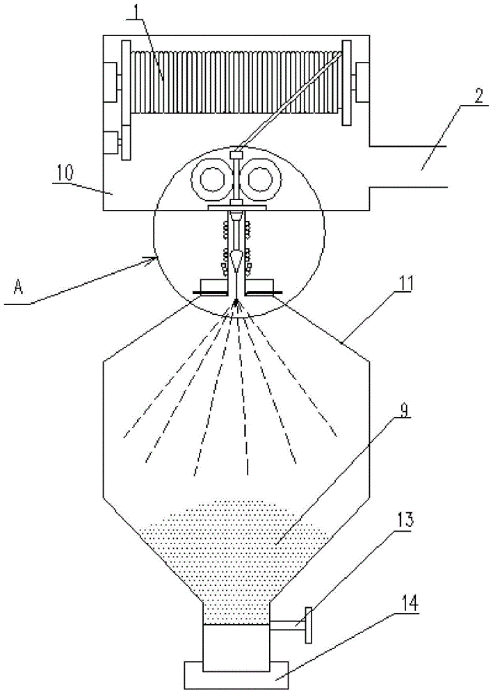
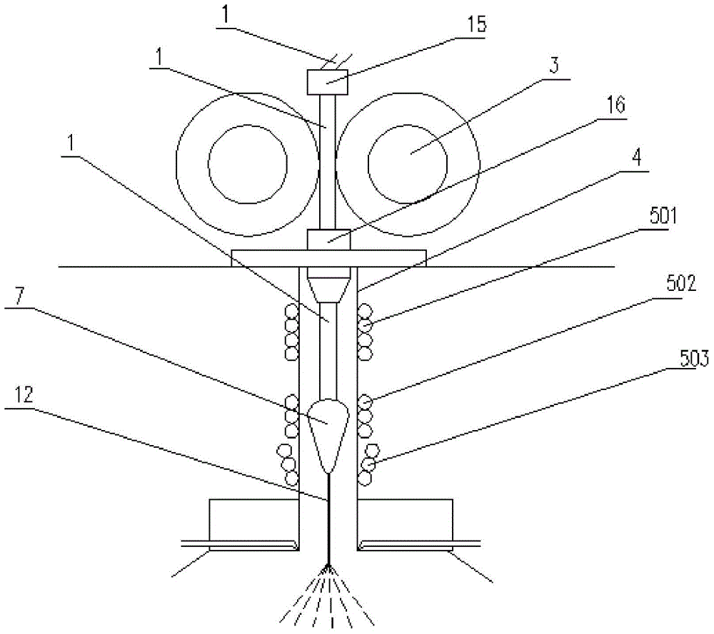
[0071] A metal powder preparation device based on controllable magnetic levitation smelting technology, such as figure 2 and 3 shown, including:
[0072] A vacuum chamber 10, the vacuum chamber 10 is provided with an air suction port 2 and a wire outlet 6, and the air suction port 2 is connected to a vacuum suction device;
[0073] The vacuum cavity 10 is provided with a roller shaft, a wire guide sleeve 15, a wire guide sleeve 16 and a pair of rollers 3, the axes of the two rollers 3 are parallel, the rotation directions of the two rollers 3 are opposite, and the two rollers 3 The gap between the rotating surfaces matches the diameter of the metal wire 1; the axes of the wire guide sleeve 15, the wire guide sleeve 16 and the quartz glass tube 4 are collinear; the wire 1 is wound on the roller shaft and wound on the roller shaft Driven by the two rollers 3, the wire 1 passes through the wire inlet guide sleeve 15, the gap between the two rollers 3, the wire outlet guide sle...
PUM
 Abstract
Description
Claims
Application Information