
A dc/dc converter parallel outer loop current sharing control method
A flow control and converter technology, applied in the field of DC/DC converter parallel outer loop current sharing control, can solve the problem that the DC circulating current does not involve the design of the current sharing controller, and achieve the effect of good robust performance
- Summary
- Abstract
- Description
- Claims
- Application Information
AI Technical Summary
Problems solved by technology
Method used
Image

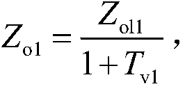
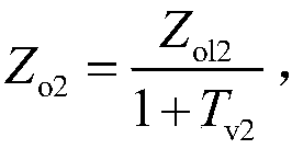

Examples
Embodiment Construction
[0037] The present invention will be described in more detail below with reference to the accompanying drawings.
[0038] combined with figure 1 The two-module Buck converter and its parallel system shown are taken as an example for illustration. In a single Buck conversion, the collector of the power device VT1 (VT2) is connected to the positive terminal of the DC power supply, and the emitter of VT1 (VT2) is connected to the cathode of the diode D1 (D2) and one end of the inductor L1 (L2). The anode of the diode D1 (D2) is connected to the negative end of the DC power supply, the other end of the inductor L1 (L2) is respectively connected to the positive end of the filter capacitor C1 (C2), and connected to the positive end of the load Z, the filter capacitor C1 (C2) Both the negative terminal and the negative terminal of Z are connected together with the negative terminal of the DC power supply. Among them L1 (L2) and C1 (C2) constitute a typical LC filter.
[0039] In o...
PUM
 Abstract
Description
Claims
Application Information