
Suspended ceiling system, secondary suspended ceiling section bar and splicing method

A technology of ceiling and profiles, which is applied in the field of secondary ceiling profiles, splicing, and ceiling systems, and can solve the problems of losing installation vertical walls and so on

Active Publication Date: 2015-04-22
佛山市南海区沙隆装饰材料有限公司
View PDF7 Cites 4 Cited by
  • Summary
  • Abstract
  • Description
  • Claims
  • Application Information

AI Technical Summary

Problems solved by technology

Graphics with traditional cultural connotations such as octagons and hexagons have hypotenuses, and the metal ceiling needs to be cut to achieve the hypotenuses of the graphics. However, the metal ceiling after cutting has lost the installation wall, so it is difficult to pass through the existing metal ceiling. Implementation of ceiling and secondary ceiling profiles

Method used


Image

  • Suspended ceiling system, secondary suspended ceiling section bar and splicing method
  • Suspended ceiling system, secondary suspended ceiling section bar and splicing method
  • Suspended ceiling system, secondary suspended ceiling section bar and splicing method

Examples


Embodiment 1

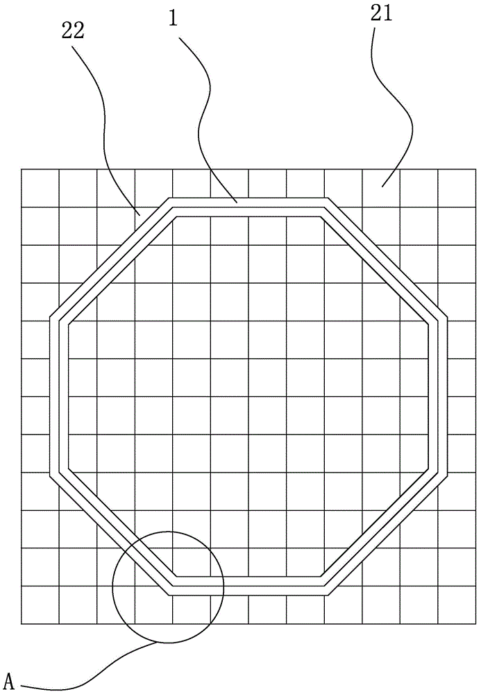
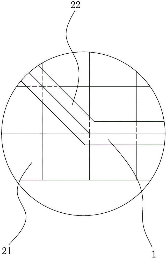
[0028] Such as figure 1 and 2 As shown, the ceiling system uses the secondary ceiling profile 1 as an outline to form an octagon. The octagon as shown has vertical or horizontal orthogonal sides, and a hypotenuse at a 45° angle to the orthogonal sides. The orthogonal side is connected to the integral metal ceiling 21 , and the hypotenuse is connected to the metal ceiling block 22 , and the metal ceiling block 22 is cut from the integral metal ceiling 21 along a diagonal line.

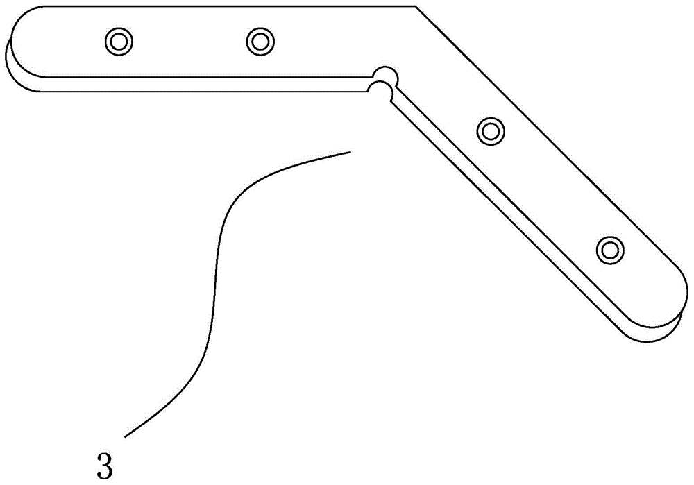
[0029] As a further preferred embodiment, the secondary ceiling profiles located at the corners of the octagonal outline are connected by a corner code of 135°. Such as image 3 and 4 Shown, described angle code comprises flat angle code 3 and vertical angle code 3 '. Since the traditional ceiling system only has right-angle graphics, there are only 90° corner angles correspondingly.

[0030] A splicing method for a ceiling system, comprising the following steps:

[0031] A. Measure the area of ​...

Embodiment 2

[0041] Such as Figure 5 As shown, the upper side of the lower wall body 18 is provided with a corner code slot for inserting a vertical corner code.

Embodiment 3

[0043] Such as Figure 6 As shown, the upper side of the lower wall body 18 is provided with a corner code slot for inserting a vertical corner code, and the decorative surface 14 is connected to the upper wall body 11 and continues to extend a part to the left to enhance the artistic effect. The upper surface of the upper wall body 11 is also provided with a corner code slot for flushing into the vertical corner code.


PUM


Abstract

The invention discloses a suspended ceiling system which comprises a metal suspended ceiling plate and a secondary suspended ceiling section bar. The secondary suspended ceiling section bar is in a geometric plane shape formed by splicing outline lines and provided with obtuse angles or acute angles. The invention further discloses a splicing method of the suspended ceiling system and the secondary suspended ceiling section bar. The suspended ceiling system is in the geometric plane shape provided with the obtuse angles or the acute angles, and the convention that a traditional suspended ceiling system is only in a right-angled side shape is broken through. The suspended ceiling system is achieved by means of the unique secondary suspended ceiling section bar and the novel splicing method, and the technical problem that the metal suspended ceiling plate is difficult to use after being cut can be solved. The suspended ceiling system, the splicing method of the suspended ceiling system and the secondary suspended ceiling section bar can be used for interior finish.

Description

technical field [0001] The invention relates to the field of building construction, in particular to a ceiling system, a secondary ceiling profile, and a splicing method. Background technique [0002] The metal ceiling includes a rectangular bottom plate and the four sides of the bottom plate are used for clamping installation vertical walls, and the secondary ceiling profiles also have installation vertical walls. The adjacent and close installation vertical walls are clamped by joists to realize the connection between the metal ceiling and the metal ceiling / secondary ceiling profiles, thereby constructing a multi-level ceiling system. Since the connection between the metal ceiling and the second-level ceiling profiles must be installed through the keel clamping to install the vertical wall, the existing ceiling system is basically spliced ​​into a figure with right-angled sides. Graphics with traditional cultural connotations such as octagons and hexagons have hypotenuses...

Claims


Application Information

Patent Timeline
Patent Type & Authority Applications(China)
IPC IPC(8): E04B9/00E04B9/06E04B9/12
Inventor 李新平
Owner 佛山市南海区沙隆装饰材料有限公司
Learn More