A rotor five-degree-of-freedom suspension structure realized by axial magnetic bearing

A technology of axial magnetic bearing and suspension structure, applied in the direction of shaft and bearing, bearing, mechanical equipment, etc., can solve the problems of inability to realize regulation, complex radial structure, unoptimized space volume and system power consumption, etc. Achieve the effect of simultaneous active control and simplification of the support structure

Active Publication Date: 2017-10-31
SHANDONG UNIV
View PDF12 Cites 0 Cited by
  • Summary
  • Abstract
  • Description
  • Claims
  • Application Information

AI Technical Summary

Problems solved by technology

[0005] (1) Electromagnetic bearing (or hybrid magnetic bearing) structure is used in both radial and axial directions. In this structure, five degrees of freedom need to be equipped with corresponding displacement sensors, power amplifiers, controllers and other hardware. In addition to increasing space and weight, It will also increase the power consumption of the system. The use of permanent magnetic bearings will take up space and increase weight
[0006] (2) Radial permanent magnetic bearing and axial magnetic bearing (or hybrid magnetic bearing) structure, because this structure uses radial permanent magnetic bearing, so the radial displacement sensor and control hardware are omitted, but radial displacement sensor and control hardware are still required. To support the bearing to achieve radial suspension
The characteristic of the above structure is that although the active degree of freedom is reduced, the radial structure is still relatively complicated. In addition, the active magnetic bearings of each degree of freedom control their respective degrees of freedom, and it is impossible to realize the suspension of a single degree of freedom magnetic bearing to multiple degrees of freedom. to regulate
[0008] To sum up, none of the above magnetic levitation structures minimizes the degree of freedom of active control (1), so that the space volume and system power consumption are not optimized.

Method used


Image

  • A rotor five-degree-of-freedom suspension structure realized by axial magnetic bearing
  • A rotor five-degree-of-freedom suspension structure realized by axial magnetic bearing
  • A rotor five-degree-of-freedom suspension structure realized by axial magnetic bearing

Examples


Embodiment Construction

[0035] The specific implementation manners of the present invention will be further described in detail below in conjunction with the accompanying drawings and embodiments.

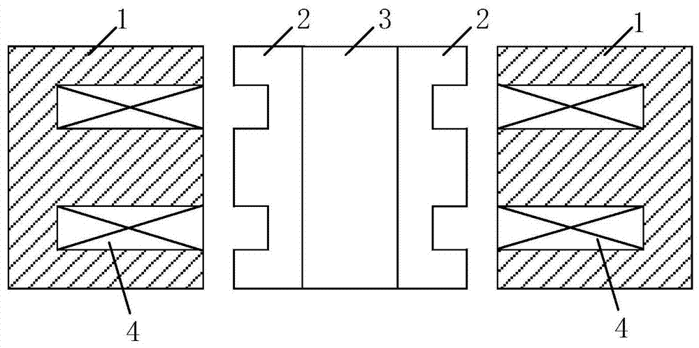
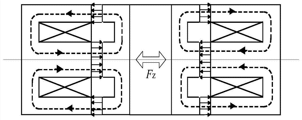
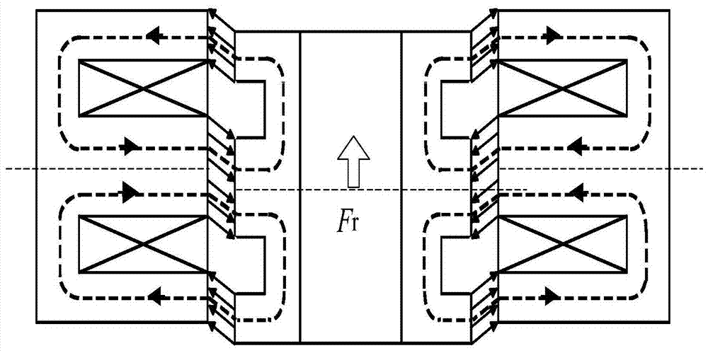
[0036] The schematic diagram of the five-degree-of-freedom suspension structure realized by the axial magnetic bearing of the present invention is as follows figure 1 and image 3 As shown, it includes axial magnetic bearings arranged at both axial ends, a rotor 3 , an axial displacement sensor 5 and a radial displacement sensor 6 , a controller 7 and a power amplifier 8 . The specific components of each part are as follows:

[0037] The axial magnetic bearings on both sides can be electromagnetic bearings. The electromagnetic bearing is composed of a stator core 1 and an electromagnetic coil 4 wound therein. The inner side of the stator core 1 is a cylindrical magnetic pole, and the coil 4 is wound between the inner and outer magnetic poles.

[0038] The rotor 3 includes magnetic poles on both sides an...


PUM


Abstract

The invention discloses a five-degree-of-freedom levitation structure of a rotor realized by an axial magnetic bearing, which includes a magnetic levitation rotor, and axial magnetic bearings are respectively arranged at both axial ends of the magnetic levitation rotor to provide the rotor axial and radial levitation forces. The axial magnetic bearings at both axial ends of the rotor are symmetrically distributed; axial displacement sensors are respectively arranged at the axial or radial ends of the rotor, and the axial displacement sensors are connected to the controller, and the controller communicates with the magnetic levitation rotor axial Axial magnetic bearing connections at both ends. The invention has beneficial effects: the active control degree of freedom of the magnetic levitation system is reduced to the minimum, the controller, power amplifier, electromagnetic coil and other components required for redundant active degree of freedom control are omitted, and the supporting structure of the five-degree-of-freedom magnetic levitation bearing is simplified.

Description

technical field [0001] The invention relates to a magnetic levitation structure, in particular to a levitation structure with five degrees of freedom of a rotor realized by an axial magnetic bearing. Background technique [0002] Magnetic suspension bearing, also referred to as magnetic bearing for short, is an electromechanical device that uses the magnetic force interaction between the stator and the rotor to support the rotor to suspend in space. Since there is no mechanical contact between the rotor and the stator, the rotor of the magnetic suspension bearing can reach a very high speed, and has the advantages of no mechanical wear, low power consumption, low noise, long life, no lubrication, etc., especially suitable for high speed, vacuum, Special applications such as ultra-clean and nuclear power. [0003] In order to realize the non-contact support of the magnetic suspension bearing system to the rotor, it needs to control its five degrees of freedom in space. The ...

Claims


Application Information

Patent Timeline
Patent Type & Authority Patents(China)
IPC IPC(8): F16C32/04
Inventor 张云鹏薛博文刘淑琴
Owner SHANDONG UNIV
Why Eureka
Try Eureka