Headrest support and locking member which is assembled to headrest support

a technology for supporting the headrest and locking member, which is applied in the field of headrest support, can solve the problems of insufficient or less optimal structure in the literature 1

Inactive Publication Date: 2006-07-27
NIPPON TECH CO LTD
View PDF9 Cites 11 Cited by
  • Summary
  • Abstract
  • Description
  • Claims
  • Application Information

AI Technical Summary

Benefits of technology

[0013] The constitution disclosed in the above-mentioned literature 1 can cope with the situation when the headrest is small-sized and a distance from the seat to the headrest is short, that is, an elevation height is low. The reason is that when the headrest is small-sized, it is possible to cope with the situation by making the stays and / or brackets and holder portions (support structure) which support the headrest light-weighted and compact. Further, in a state that the elevation height is low, it is possible to simplify the support structure. However, under a current situation which aims at the enhancement of safety, functionality and the like by increasing a size of the headrest or under a current situation in which the elevation height of the headrest is increased so as to prevent a driver from suffering from whiplash at the time of collision and damages on his / her neck portion (in other words, the elevation height being low currently), the constitution disclosed in the literature 1 is not sufficient or less than optimal. Further, in holding the headrest at the high elevation height, it is a prerequisite to ensure the large support structure so as to firmly support (hold and / or press or the like), while in the prevention of the rattling sounds, it is a prerequisite to eliminate gaps in the support structure so as to firmly and resiliently support the headrest.

Problems solved by technology

However, under a current situation which aims at the enhancement of safety, functionality and the like by increasing a size of the headrest or under a current situation in which the elevation height of the headrest is increased so as to prevent a driver from suffering from whiplash at the time of collision and damages on his / her neck portion (in other words, the elevation height being low currently), the constitution disclosed in the literature 1 is not sufficient or less than optimal.
However, to consider (A) large-sizing of the headrest and (B) the structure which increases the elevation height into consideration, the structure disclosed in the literature 2 is not sufficient or less than optimal.
Further, when given vehicle types and / or given conditions (the assurance of further comfortable ride and tranquility) are taken into consideration, the structure disclosed in the literature 2 is not sufficient or less than optimal.

Method used


Image

  • Headrest support and locking member which is assembled to headrest support
  • Headrest support and locking member which is assembled to headrest support
  • Headrest support and locking member which is assembled to headrest support

Examples


Embodiment Construction

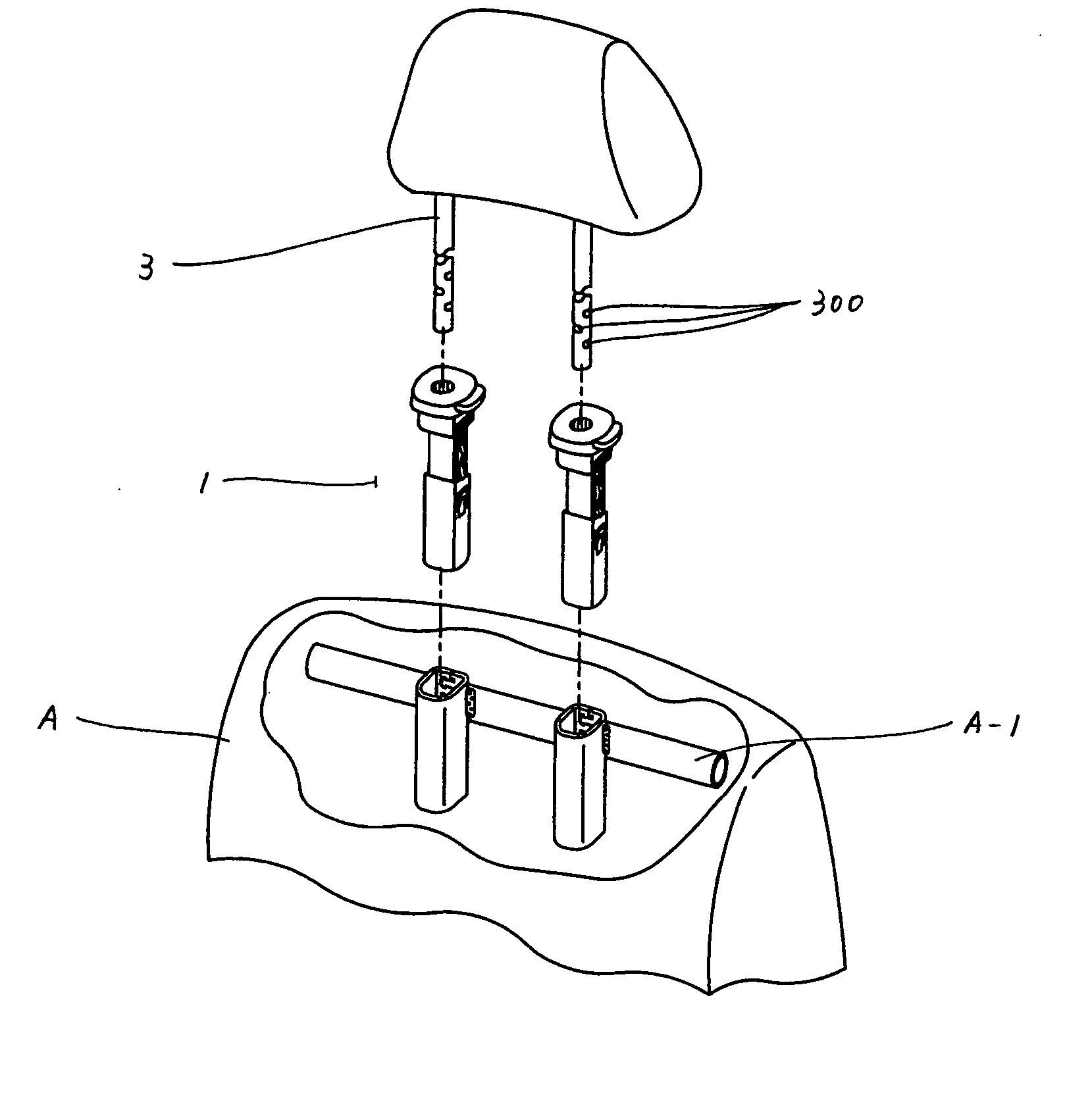
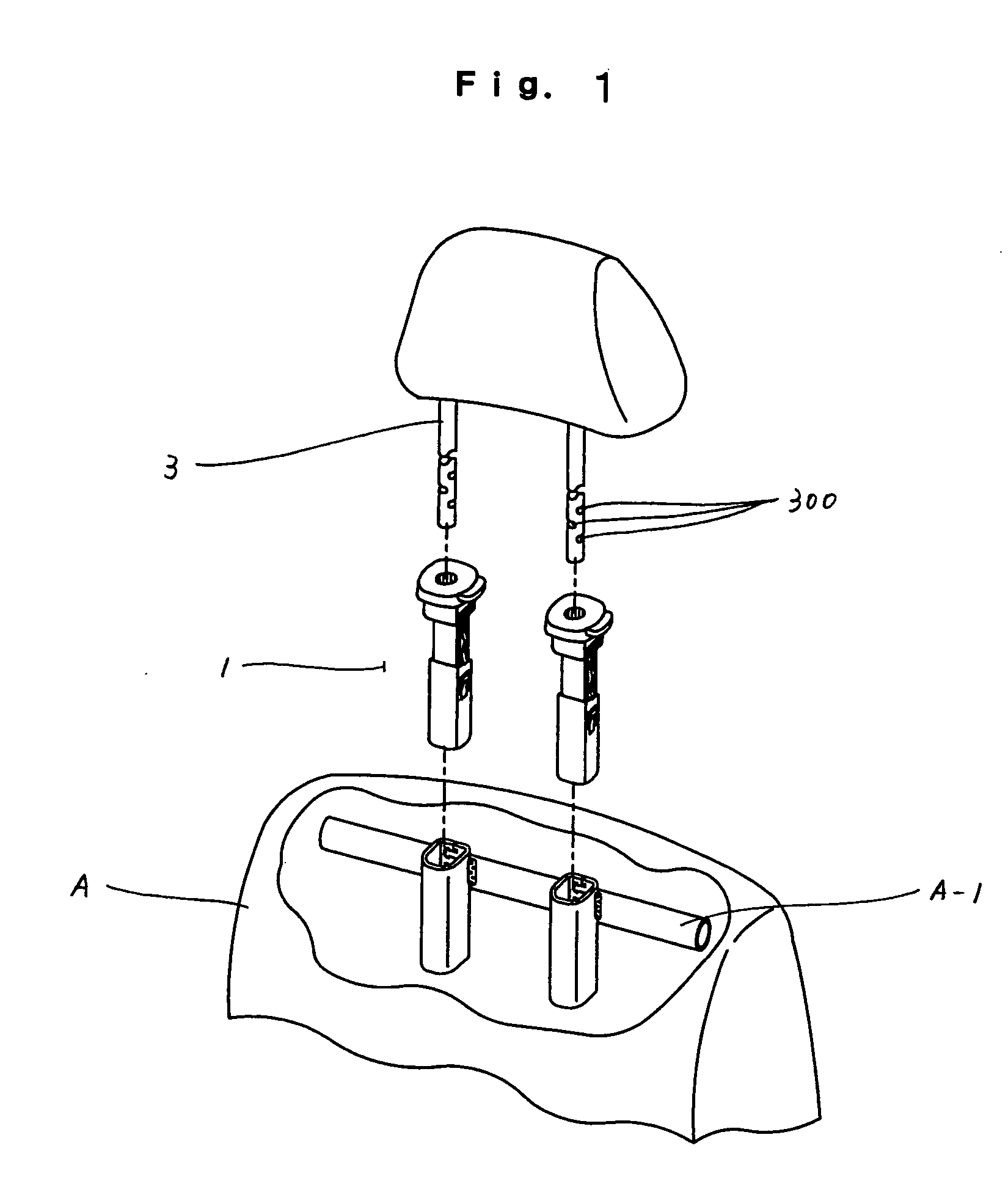
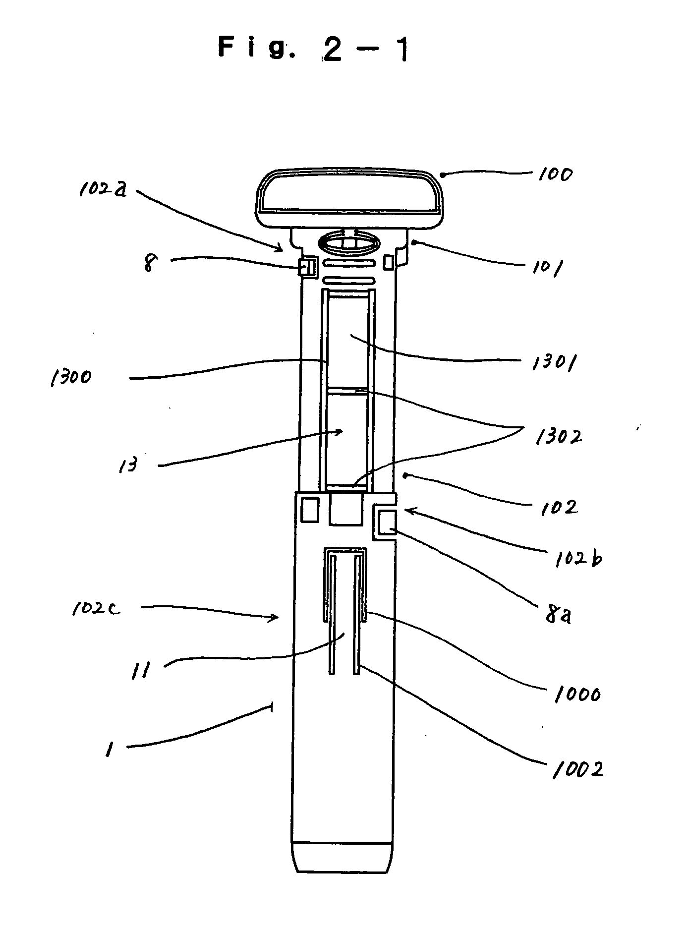
[0061] First of all, drawings are explained. FIG. 1 is a reduced-scale schematic view showing the relationship among a headrest support, a headrest, a receiving member and a seat; FIG. 2-1 is a front view of the headrest support; FIG. 2-2 is a back view of the headrest support; FIG. 3 is a cross-sectional view of FIG. 2-1; FIG. 4 is a front view showing a state in which the headrest support is fitted in a receiving member; FIG. 5 is an enlarged front view of an essential part showing the headrest support, and a head portion, a neck portion and a barrel portion of the headrest; FIG. 6 is a cross-sectional view taken along a line A-A in FIG. 5; FIG. 7 is a cross-sectional view taken along a line B-B in FIG. 5; FIG. 8 is a cross-sectional view taken along a line C-C in FIG. 5; FIG. 9-1 is a view as viewed from P1 in FIG. 7; FIG. 9-2 is a view as viewed from P2 in FIG. 7; FIG. 10 is a view as viewed from P3 in FIG. 7; FIG. 11 is a plan view showing an example of a locking member; FIG. 1...


PUM


Abstract

A headrest support holds a headrest arranged on a seat by fitting engagement, is supported on a receiving member formed on the seat, and has a through hole for fitting stay of the headrest therein. The headrest support is constituted of an approximately umbrella-like head portion, a neck portion which is formed below the head portion, and an approximately cylindrical barrel portion arranged below the neck portion, wherein the head portion, the neck portion and the barrel portion are formed integrally. A stay-and-receiving-member pressing portion having resiliency is formed by forming a first cut groove in an intermediate portion of the barrel portion and by setting the stay-and-receiving-member pressing portion free in at least two directions from the barrel portion. The stay-and-receiving-member pressing portion is formed in an arcuate shape as viewed in a cross section, wherein a curved inner surface which is curved toward a stay side is formed at a center portion of a curved inner surface, and a projecting outer surface which projects toward the receiving member side is formed on a curved outer surface end portion. And one or plural pairs of resilient members are respectively formed on an upper portion and an intermediate portion of the barrel portion. An outer peripheral portion of the stay is pressed by the curved inner surface and an inner surface of the receiving member is pressed by the projecting outer surface and / or the respective pairs of the resilient members.

Description

BACKGROUND OF THE INVENTION [0001] 1. Field of the Invention [0002] The present invention relates to a headrest support which supports a headrest of a seat of various transport means (vehicle, airplane, vessel and the like), and more particularly to a headrest support which can support a headrest which is mounted on the transport means by way of a receiving member and / or a headrest stay by completely eliminating a play of the headrest (setting the play to approximately zero) and a locking member which is assembled to the headrest support. [0003] 2. Description of the Related Art [0004] With respect to this type of transport means, particularly with respect to the vehicle, along with the lapse of time, demands for the safety, the comfortable ride, the easiness of manipulation or driving and the like have been changed and hence, various improvements have been made to meet the demands. With such improvements, it is possible to enhance the safety, the comfortable ride, the tranquility o...

Claims


Application Information

Patent Timeline
Patent Type & Authority Applications(United States)
IPC IPC(8): A47C7/36
CPCB60N2/4817B60N2002/4897B60N2205/20B60N2/818B60N2/897
Inventor YAMADA, NOBUO
Owner NIPPON TECH CO LTD
Why Eureka
Try Eureka