
A scheduling method for software-defined network controller clusters

A software-defined network and controller cluster technology, applied in the network field, can solve problems such as low processing performance, affecting the operation of the overall network system, performance bottlenecks of third-party managers, etc., to achieve the effect of improving performance and efficiency

Active Publication Date: 2018-01-05
GUANGZHOU BINGO SOFTWARE
View PDF8 Cites 0 Cited by
  • Summary
  • Abstract
  • Description
  • Claims
  • Application Information

AI Technical Summary

Problems solved by technology

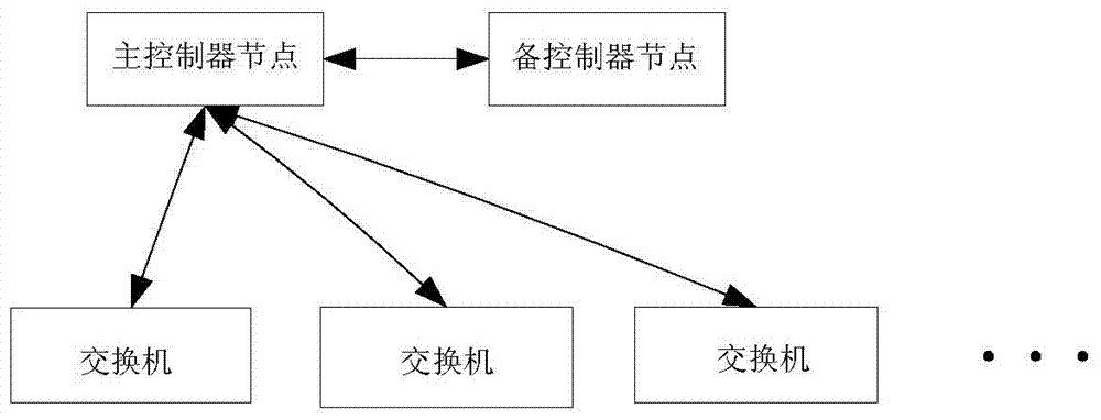
[0002] At present, there are roughly two scheduling schemes for software-defined network (Software Defined Network, SDN) controllers. One is a scheduling scheme based on dual-machine hot standby. Its architecture is as follows figure 1 As shown, usually the master controller node is responsible for taking over all the switches, and when the master controller node is down, the standby controller node takes over all the switches; the disadvantage is that the load pressure is concentrated on a single controller node, processing low performance
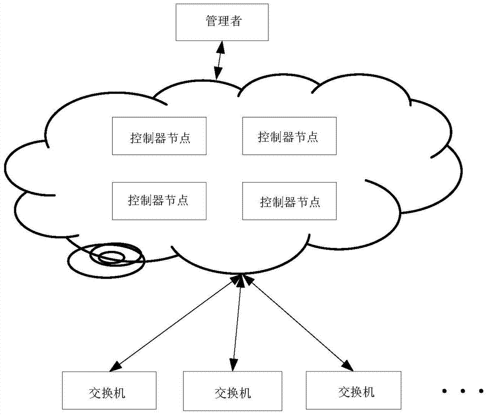
[0003] The other is to use a third-party manager to schedule the controller cluster. Its architecture is as follows: figure 2 As shown in , add a third-party manager besides all controller nodes, responsible for managing and scheduling all controller nodes in the cluster; all controller nodes assign switch takeover tasks through this third-party manager; if the controller When a node goes down, the third-party manager will reschedule the switch to take over the task; the disadvantage is that if the third-party manager goes down, it will affect the operation of the overall network system. The program scheduling performance of the third-party manager will make the performance of the third-party manager become the bottleneck of the overall cluster

Method used


Image

  • A scheduling method for software-defined network controller clusters
  • A scheduling method for software-defined network controller clusters
  • A scheduling method for software-defined network controller clusters

Examples


Embodiment Construction

[0035] In order to facilitate the understanding of those skilled in the art, the present invention will be further described below with reference to the accompanying drawings and embodiments.

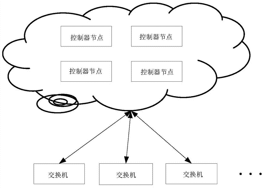
[0036] An embodiment of the scheduling method of a software-defined network controller cluster proposed by the present invention, please refer to image 3 , The software-defined network controller cluster includes several controller nodes (at least two controller nodes); each controller node has a corresponding Hash table, and the data of each Hash table includes: Identification, the identification of the switch that each controller node is responsible for taking over, and the load factor of each controller node; where each controller node is only allowed to modify the identification and load factor of the switch that it is responsible for taking over in the Hash table it owns; When each controller node modifies the data in the Hash table it owns, it needs to synchronize the modified data t...


PUM


Abstract

The invention relates to a scheduling method of a software-defined network controller cluster, which adopts the scheme of the controller cluster, can distribute the load pressure to each controller node, and avoids the processing performance that is caused by concentrating all the load pressure on a single controller node. low problem. Each controller node in the cluster is configured with a corresponding Hash table. Each controller node is only allowed to modify the identity of the switch it is responsible for taking over and its load factor in the Hash table it owns. Each controller node modifies its When the data in the owned Hash table, need its modified data synchronously in other controller nodes, update the data in the Hash table that owns respectively by other controller nodes correspondingly; The present invention can determine corresponding according to the data in the Hash table The controller node takes over the switch without introducing a third-party manager, and will not cause the entire cluster to be limited by the performance of the third-party manager.

Description

Technical field [0001] The invention relates to the field of network technology, in particular to a software-defined network controller cluster scheduling method. Background technique [0002] At present, the software-defined network (Software Defined Network, SDN) controller has two scheduling schemes. One is the scheduling scheme based on dual-system hot standby, and its architecture is as follows: figure 1 As shown, the main controller node is usually responsible for taking over all the switches. When the main controller node is down, the standby controller node takes over all the switches; the disadvantage is that the load pressure is concentrated on a single controller node. Performance is low. [0003] The other is the scheduling scheme of the controller cluster through a third-party manager, and its architecture is as figure 2 As shown, in addition to all controller nodes, a third-party manager is added to manage all controller nodes in the scheduling cluster; all controlle...

Claims


Application Information

Patent Timeline
Patent Type & Authority Patents(China)
IPC IPC(8): H04L12/743H04L29/08
Inventor 董栓宗林冬艺
Owner GUANGZHOU BINGO SOFTWARE
Learn More