
A fault warning signal display method for automobiles

A technology of warning signal and display method, which is applied to optical signals, signal devices, vehicle components, etc., can solve the problems of failure to warn, and the placement of fault warning signs is unsafe, and achieves the effect of ensuring personal safety.

Active Publication Date: 2017-05-03
HASCO VISION TECHNOLOGY CO LTD
View PDF2 Cites 0 Cited by
  • Summary
  • Abstract
  • Description
  • Claims
  • Application Information

AI Technical Summary

Problems solved by technology

[0009] Although the above-mentioned technical solutions have further improved the existing vehicle failure warning signs, they are all based on the existing triangular plate-shaped member, in other words, they still do not break away from the triangular plate of the existing vehicle failure warning signs. This has brought a lot of problems to car drivers. One is that many cars often do not carry vehicle failure warning signs with them, which may violate relevant regulations; When a traffic accident is caused by a fault warning sign, the driver has to bear serious consequences; the second is that many vehicle fault warning signs are just simple triangular signs, which will be blown away when the wind is strong, and cannot serve as a warning; The process of placing this fault warning sign on the highway, especially at night on the expressway, is very dangerous in itself, and the person who needs the fault warning sign to place the fault warning sign walks for a while on the road or expressway in the opposite direction (reverse direction of the lane where the faulty car is located) After a distance of 50 to 150 meters as mentioned above, the placement of the fault warning sign is carried out. This retrograde process itself has great unsafe factors for the placer of the fault warning sign.

Method used


Image

  • A fault warning signal display method for automobiles
  • A fault warning signal display method for automobiles
  • A fault warning signal display method for automobiles

Examples


Embodiment Construction

[0063] The present invention will be further described below in conjunction with the accompanying drawings and embodiments.

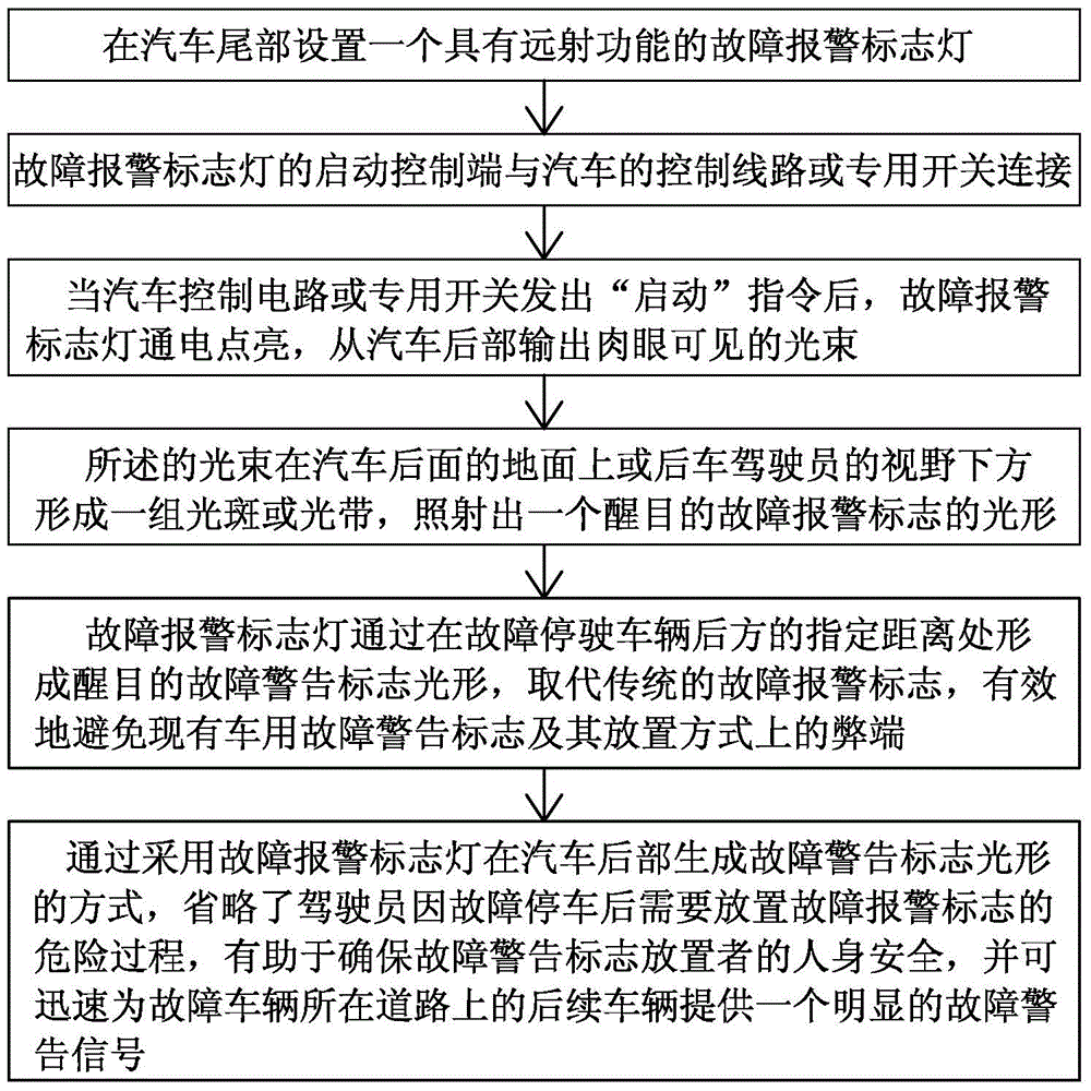
[0064] figure 1 Among them, the purpose of the present invention is to provide a fault warning signal display method for the deficiencies in the structure and setting method of the existing fault alarm signs. The light shape of the fault alarm sign replaces the traditional fault alarm sign, and also saves the dangerous process of placing the fault alarm sign after the driver stops due to a fault.

[0065] The technical scheme of the present invention provides a method for displaying a fault warning signal for automobiles, including when a fault occurs to a motor vehicle driving on a road or an expressway and needs to be parked on the road or expressway, displaying a warning signal behind the faulty automobile At the specified distance, set a fault warning signal, the invention point is:

[0066] At the rear of the car, set a fault alarm sign light wit...


PUM


Abstract

The invention discloses a fault warning signal display method for an automobile, and belongs to the field of signal display devices. The fault warning signal display method disclosed by the invention has the beneficial effects that a fault warning identification lamp with a long shot function is adopted, and red light beams can be backwards output from the tail part of the automobile, so a group of light spots or light bands are formed on the ground behind the automobile or under the view field of a driver of a behind automobile running in the same direction, and a marked fault warning mark optical diagram is irradiated or mapped, so that a dangerous process that a driver needs to place the fault warning mark due to fault parking is omitted through a way that a fault warning mark optical diagram is formed at the tail part of the fault automobile, and the personal safety of the person placing the fault warning mark is favorably ensured, besides an obvious fault warning signal can be rapidly provided for other vehicles running in the same direction behind the road where the automobile in fault parking is located, and the traffic safety and the unblocked road are favorably ensured; the fault warning signal display method can be widely applied to the field of designing and manufacturing automobile signal lamp devices.

Description

technical field [0001] The invention belongs to the field of signal display devices, in particular to a fault warning signal display method for automobiles. Background technique [0002] Adopted at the 31st meeting of the Standing Committee of the Tenth National People's Congress of the People's Republic of China on December 29, 2007, the 50th "Road Traffic Safety Law of the People's Republic of China" came into effect on May 1, 2008 Article 2 stipulates that when a motor vehicle breaks down on the road and needs to be stopped to troubleshoot the fault, the driver should immediately turn on the hazard warning lights and move the motor vehicle to a place that does not hinder traffic; if it is difficult to move, the driver should continue to turn on the danger warning lights , and set up warning signs and other measures in the direction of approaching vehicles to expand the warning distance; it is stipulated in Article 68 that: when a motor vehicle breaks down on the expresswa...

Claims


Application Information

Patent Timeline
Patent Type & Authority Patents(China)
IPC IPC(8): B60Q1/30B60Q1/50
Inventor 曹阳褚晓峰周晓军袁晓岗郭田忠
Owner HASCO VISION TECHNOLOGY CO LTD
Learn More