Double-stage compressor

A two-stage compressor, one-stage technology, applied in the direction of mechanical equipment, machine/engine, pump combination for elastic fluid rotary piston type/oscillating piston type, etc., can solve the problem of insufficient air intake of high-pressure stage cylinders, compressors Problems such as limited displacement and impact on compressor performance, to achieve the effect of keeping the suction and exhaust process smooth and avoiding pulsation

Active Publication Date: 2015-05-20
ZHUHAI GREE REFRIGERATION TECH CENT OF ENERGY SAVING & ENVIRONMENTAL PROTECTION
View PDF5 Cites 7 Cited by
  • Summary
  • Abstract
  • Description
  • Claims
  • Application Information

AI Technical Summary

Problems solved by technology

[0003] Since the low-pressure cylinder and high-pressure cylinder of the current two-stage compression cylinder only contain one cylinder, the displacement of the entire compressor is relatively limited, which is increasingly unable to meet the use environment of large-scale temperature regulation, and the current two-stage compression cylinder The suction connection between the middle and low-pressure cylinders and the high-pressure cylinders is not reasonable enough. It often happens that when the high-pressure cylinder is at the suction peak, the low-pressure cylinder does not reach the exhaust peak position or is far away from the exhaust peak position; Or when the suction rate of the high-pressure stage cylinder is low, the low-pressure stage cylinder is already at the exhaust peak position, these situations will cause the suction and exhaust pulsation between the high and low pressure stages, and the continuity of the suction and exhaust between the low pressure stage and the high pressure stage It will directly affect the performance of the compressor. When the first-stage compressed gas cannot be inhaled by the high-pressure stage cylinder in time, the first-stage compressed gas will accumulate in the intermediate chamber and cause the pressure of the intermediate chamber to rise; and when the high-pressure stage cylinder is at the suction peak If the low-pressure stage cylinder is far from reaching the exhaust peak value, this will lead to insufficient air intake of the high-pressure stage cylinder, resulting in a decline in compressor performance

Method used


Image

  • Double-stage compressor
  • Double-stage compressor
  • Double-stage compressor

Examples


Embodiment 1

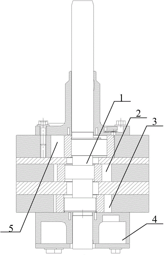
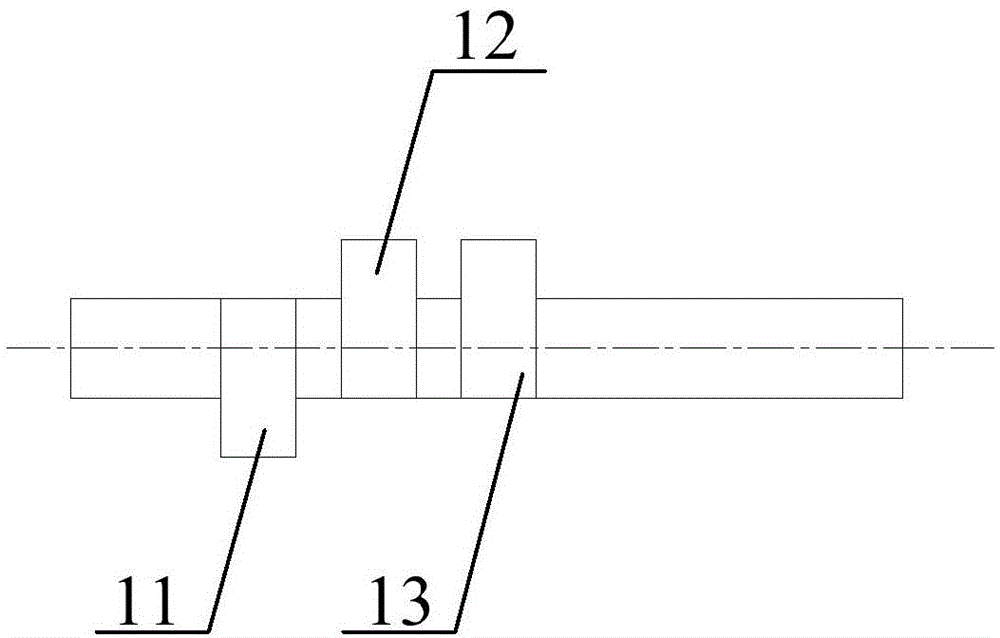
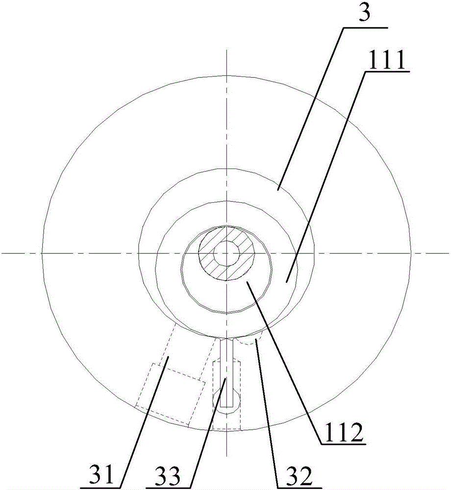
[0048] Please refer to Figure 1 to Figure 5 , figure 1 Is a partial cross-sectional schematic diagram of a two-stage compressor, figure 2 Is a schematic diagram of the crankshaft in the first embodiment, image 3 Is a schematic top view of the first cylinder in the first embodiment, Figure 4 Is a schematic top view of the second cylinder in the first embodiment, Figure 5 It is a schematic top view of the high-pressure cylinder in the first embodiment.

[0049] In the embodiment of the present invention, for convenience of description, the eccentric part in the first eccentric assembly 11 in the first cylinder 3 is named the first eccentric part 112, and the eccentric part in the second eccentric assembly 12 in the second cylinder 2 is named The eccentric part is named the second eccentric part 122, and the eccentric part in the high-pressure eccentric assembly 13 in the high-pressure stage cylinder 5 is named the high-pressure eccentric part 132; the first eccentric assembly 11...

Embodiment 2

[0053] Such as Image 6 As shown in the figure, taking the first eccentric portion 112 as a reference, the angle between the second eccentric portion 122 and the first eccentric portion 112 is 180°, and the angle between the high-voltage eccentric portion 132 and the second eccentric portion 122 is 180° °. It should be noted that the top view of the first cylinder 3 and the top view of the second cylinder 2 in this embodiment are the same as those in the first embodiment, so please refer to the top view of the first cylinder 3 in this embodiment image 3 , Please refer to the top view of the second cylinder 2 Figure 4 .

[0054] Please also refer to Figure 7 , Figure 7 This is a schematic top view of the high-pressure stage cylinder in the second embodiment. Because the angle between the second eccentric portion 122 and the first eccentric portion 112 is 180°, in order to ensure that the first cylinder 3 and the second cylinder 2 start air intake The phase difference is 180° t...

Embodiment 3

[0057] Such as Figure 8 As shown in the figure, taking the first eccentric portion 112 as a reference, the angle between the second eccentric portion 122 and the first eccentric portion 112 is 0°, and the angle between the high-voltage eccentric portion 132 and the first eccentric portion 112 is 180 °. It should be noted that the top view schematic view of the first cylinder 3 in this embodiment is the same as that in the first embodiment, and the top view schematic view of the high-pressure stage cylinder 5 is the same as that in the first embodiment. Please refer to the top view image 3 , Please refer to the top view of the high-pressure cylinder 5 Figure 5 .

[0058] Please also refer to Picture 9 , Picture 9 This is a schematic top view of the second cylinder in the third embodiment. Because the angle between the second eccentric portion 122 and the first eccentric portion 112 is 0°, in order to ensure that the first cylinder 3 and the second cylinder 2 start air intake ...


PUM


Abstract

The invention discloses a double-stage compressor. The double-stage compressor comprises a low-pressure-stage air cylinder and a high-pressure-stage air cylinder, wherein the low-pressure-stage air cylinder comprises a first air cylinder and a second air cylinder, which are arranged in the axis direction of the compressor, the phase difference of the first air cylinder and the second air cylinder at an air inlet beginning time falls in a range of 120 to 240 degrees, and the phase difference of the high-pressure-stage air cylinder and one of the first air cylinder and the second air cylinder at the air inlet beginning time falls in a range of 120 to 240 degrees or -60 to 60 degrees. By adopting the double-stage compressor, not only can the problem that the gas displacement of the double-stage compressor is limited be effectively solved, but also the simultaneous occurrence of an air suction peak value of the two air cylinders in the low-pressure-stage air cylinder can be avoided; moreover, when the high-pressure-stage air cylinder stays nearby the air suction peak value position, the two air cylinders at the lower-pressure stage can successively reach an exhaust peak value position, so that the air suction process and the exhaust process of the compressor can be maintained smooth, and the severe fluctuation of the compressor in the suction and exhaust processes can be avoided.

Description

Technical field [0001] The invention relates to the technical field of air conditioning compressor preparation, and more specifically, to a multi-cylinder two-stage compressor. Background technique [0002] The current rolling-rotor two-stage compressor generally includes a low-pressure stage cylinder and a high-pressure stage cylinder. The low-pressure stage cylinder forms a first-stage compressed gas after completing the first-stage compression, and the high-pressure The compressed gas undergoes secondary compression to form a secondary compressed gas. [0003] Since both the low-pressure cylinder and the high-pressure cylinder of the current two-stage compression cylinder contain only one cylinder, the displacement of the entire compressor is relatively limited, which is increasingly unable to meet the use environment of large-scale temperature adjustment, and the current two-stage compression cylinder The suction connection between the medium and low-pressure stage cylinders a...

Claims


Application Information

Patent Timeline
Patent Type & Authority Applications(China)
IPC IPC(8): F04C23/00
Inventor 王大号黄辉胡余生魏会军梁社兵朱红伟刘靖杨欧翔吴健任丽萍邹鹏
Owner ZHUHAI GREE REFRIGERATION TECH CENT OF ENERGY SAVING & ENVIRONMENTAL PROTECTION
Why Eureka
Try Eureka