Environment electromagnetic radiation monitoring system

An electromagnetic radiation and monitoring system technology, applied in the direction of electromagnetic field characteristics, can solve the problems of high price, large power consumption, and bulky volume, and achieve the effect of simple operation and low energy consumption

Active Publication Date: 2015-05-20
BEIJING UNIV OF POSTS & TELECOMM
View PDF7 Cites 8 Cited by
  • Summary
  • Abstract
  • Description
  • Claims
  • Application Information

AI Technical Summary

Problems solved by technology

[0004] 1. Its radio frequency performance is often higher than the electromagnetic monitoring requirements of the home environment, so its cost is high, and its processor often has high performance, resulting in unnecessary waste;
[0005] 2. The signal processing process is complex, including a large number of AD sampling and digital signal processing processes, which need to consume a lot of resources to complete the work;
[0006] 3. It is bulky and not suitable for family popularization;
[0007] 4. The price is expensive, usually ranging from tens of thousands to hundreds of thousands of equipment;
[0008] 5. High power consumption, in order to achieve its radio frequency performance and digital signal processing performance, the process needs to consume a lot of power

Method used


Image

  • Environment electromagnetic radiation monitoring system

Examples


Embodiment Construction

[0036] In order to realize the electromagnetic radiation monitoring problem in the environment, the present invention provides an environmental electromagnetic radiation monitoring system. The present invention will be further described in detail below in conjunction with the accompanying drawings and embodiments. It should be understood that the specific embodiments described here are only used to explain the present invention, not to limit the present invention.

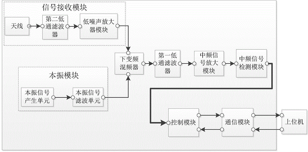
[0037] figure 1 It is a schematic structural diagram of an environmental electromagnetic radiation monitoring system in an embodiment of the present invention; as figure 1 As shown, the system uses a zero-IF approach, including:

[0038] The local oscillator module is used to generate and output a local oscillator frequency sweep signal.

[0039] The signal receiving module is used for receiving and outputting radio frequency signals of electromagnetic radiation in the environment.

[0040] The down-conversion m...


PUM


Abstract

The invention discloses an environment electromagnetic radiation monitoring system. The system comprises a local oscillator module, a signal receiving module, a down-conversion mixer, a first low-pass filter, a medium frequency signal detection module and a control module, wherein the local oscillator module is used for generating a local oscillator frequency sweeping signal; the signal receiving module is used for receiving a radio frequency signal of electromagnetic radiation in a monitored environment; the down-conversion mixer is used for mixing the local oscillator frequency sweeping signal generated by the local oscillator module and the radio frequency signal received by the signal receiving module to realize down conversion and then output a medium frequency signal; the first low-pass filter is used for filtering the medium frequency signal output by the down-conversion mixer; the medium frequency signal detection module is used for receiving the filtered medium frequency signal and converting the power of the medium frequency signal into an analog level value; the control module is used for acquiring the analog level value and converting the analog level value into a digital signal level value. The monitoring system has the characteristics of programmability, multi-functionality, easiness in operation and the like, a space environment radio frequency radiation signal can be effectively measured, signal power can be effectively and quantitatively analyzed, and the system can be applied to environment electromagnetic radiation measurement and monitoring.

Description

technical field [0001] The invention relates to the field of environmental monitoring, in particular to an environmental electromagnetic radiation monitoring system. Background technique [0002] At present, the instruments that better realize environmental electromagnetic monitoring are mainly produced by companies such as R&S, Tektronix, Anritsu, and Agilent. These environmental electromagnetic monitoring instruments are mainly aimed at professional users and high-end customers. Huge, it is difficult to popularize and apply in the family environment electromagnetic monitoring. [0003] Specifically, the application of these environmental electromagnetic monitoring instruments in household environmental electromagnetic monitoring has the following disadvantages: [0004] 1. Its radio frequency performance is often higher than the electromagnetic monitoring requirements of the home environment, so its cost is high, and its processor often has high performance, resulting in ...

Claims


Application Information

Patent Timeline
Patent Type & Authority Applications(China)
IPC IPC(8): G01R29/08
Inventor 李书芳彭彪王帅马晓元周源邓力尹良
Owner BEIJING UNIV OF POSTS & TELECOMM
Why Eureka
Try Eureka