Hidden synchronous spring lock unlocking method, key and lock cylinder

A technology of pin locks and lock cylinders, applied to cylinder pin locks, locks with turning keys, keys, etc., to achieve the effect of improving security

Active Publication Date: 2015-06-03
彭世明
View PDF5 Cites 5 Cited by
  • Summary
  • Abstract
  • Description
  • Claims
  • Application Information

AI Technical Summary

Problems solved by technology

[0003] Aiming at the existing mechanical lock cylinder, the object of the present invention is to provide a method for unlocking a hidden synchronous pin lock and the key and the lock cylinder, aiming to completely separate the inside of the lock cylinder (the part where the pins are installed) from the outside when the key is used to unlock the lock. So that there is no possibility of technical unlocking

Method used


Image

  • Hidden synchronous spring lock unlocking method, key and lock cylinder
  • Hidden synchronous spring lock unlocking method, key and lock cylinder
  • Hidden synchronous spring lock unlocking method, key and lock cylinder

Examples


Embodiment 1

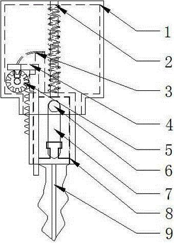
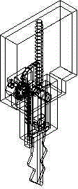
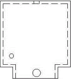
[0080] With reference to the accompanying drawings, the key of the present invention mainly includes a key handle and a corrugated part. The key handle includes a key handle shell 1, a return spring 2, a return spring sheet 3, a baffle locking member 4, a baffle locking gear 5, a cylindrical shaft 6, Baffle plate motion guide 7, baffle plate 8. The baffle locking gear 5 has two working surfaces, one is a gear surface, and the other is a cylindrical surface with a locking groove. The baffle locking gear 5 continues to rotate until the locking protrusion on the baffle locking part 4 is stuck in the locking groove on the baffle locking gear 5, and the baffle locking gear 5 passes through the shaft and the hole in the lower left corner of the key handle shell 1 Cooperate, the baffle locking gear 5 can rotate around this hole, the baffle 8 is sleeved on the baffle movement guide 7, wherein the cylindrical guide rod of the baffle movement guide 7 passes through the cylindrical hole ...

Embodiment 2

[0091] A method for unlocking a hidden synchronous tumbler lock. When a key is inserted into the keyhole to unlock the lock, the cover 13 arranged between the lock cylinder shell 10 and the lock cylinder rotor 14 is first moved into the lock cylinder rotor 14 and blocks the keyhole, and then the key The rotating lock cylinder rotor 14 is normally opened; like this, when the keyhole is opened, if the lock is unlocked abnormally, although the existence of the pin can be sensed, the specific position of the pin cannot be sensed because the lock core rotor 14 cannot effectively rotate, and when the lock core rotor 14 effectively rotates, then because the keyhole is blocked, can't sense the marble; that is, when unlocking with the key, the interior of the lock cylinder must be completely separated from the outside, so there is no possibility of technical unlocking; It is impossible to perceive the actual position of the pin by turning the pin, so it is impossible to technically unlo...


PUM


Abstract

The invention discloses a concealed synchronous pin tumbler lock. The pin tumbler lock mainly comprises a key and a lock cylinder. The key mainly comprises a key handle shell, a reset spring, a reset spring strip, a baffle locking piece, a baffle locking gear, a cylindrical shaft, a baffle motion guiding piece, a baffle and a tooth pattern part. The lock cylinder mainly comprises a lock cylinder shell, a compensation block, a spring strip, a shelter, a lock cylinder rotor, a rightward pin tumbler, a leftward pin tumbler, a lock cylinder bottom plate, a clamping spring and a spring. According to the lock cylinder in the pin tumbler lock, when the lock is opened with the key, the interior of the lock cylinder must be totally separated from the outside, and therefore the possibility of technical unlocking does not exist. Because the pin tumblers will not touch the inner wall of the lock cylinder shell, it is impossible that the actual positions of the pin tumblers are sensed by poking the pin tumblers, and therefore technical unlocking cannot be achieved through the attempt to poke the pin tumblers to the unlocking positions. The position, allowing the lock to be opened, of each pin tumbler is unique, and thus pin tumbler skip unlocking can be avoided. The shapes and the arrangement mode of the pin tumblers are changed, and thus the secret key amount of the lock is greatly increased. The technical requirement for manufacturing of the lock is not substantially raised, and thus the production cost will not be increased substantially.

Description

technical field [0001] The present invention relates to a mechanical tumbler lock, in particular to a method for unlocking a hidden synchronous tumbler lock, a key and a lock cylinder, in particular to a method for unlocking a hidden synchronous tumbler lock, a key and a lock cylinder that effectively prevent technical opening. Background technique [0002] At present, there are many shortcomings or deficiencies in the existing mechanical lock cylinders: 1. There is the possibility of technical unlocking, common methods, methods and techniques for technical unlocking: Ⅰ. Using a certain way and method to sense the position of the marbles, and to achieve the purpose of technical unlocking by fiddle with the pins so that the pins are finally in the unlocking position; Ⅱ. Use continuous attempts to fiddle with each marble to achieve the purpose of breaking each; Ⅲ. Under normal circumstances, the two marbles in the same pinhole are close together, so that the lock can only be ...

Claims


Application Information

Patent Timeline
Patent Type & Authority Applications(China)
IPC IPC(8): E05B27/06E05B19/00E05B19/08E05B15/00E05B15/14E05B17/20
Inventor 彭世明彭翔
Owner 彭世明
Why Eureka
Try Eureka