compressor wheel

A technology of compressors and superchargers, applied in mechanical equipment, engine components, machines/engines, etc., can solve the problems of air heating, low internal combustion engine power, etc., and achieve the effect of light weight

Active Publication Date: 2020-01-03
BMTS TECH SHANGHAI CO LTD
View PDF6 Cites 0 Cited by
  • Summary
  • Abstract
  • Description
  • Claims
  • Application Information

AI Technical Summary

Problems solved by technology

This has the disadvantage that the air fed to the internal combustion process is heated considerably and thus only very little oxygen is made available for the internal combustion process, so that the achievable internal combustion engine power remains relatively low

Method used


Image

  • compressor wheel
  • compressor wheel
  • compressor wheel

Examples


Embodiment Construction

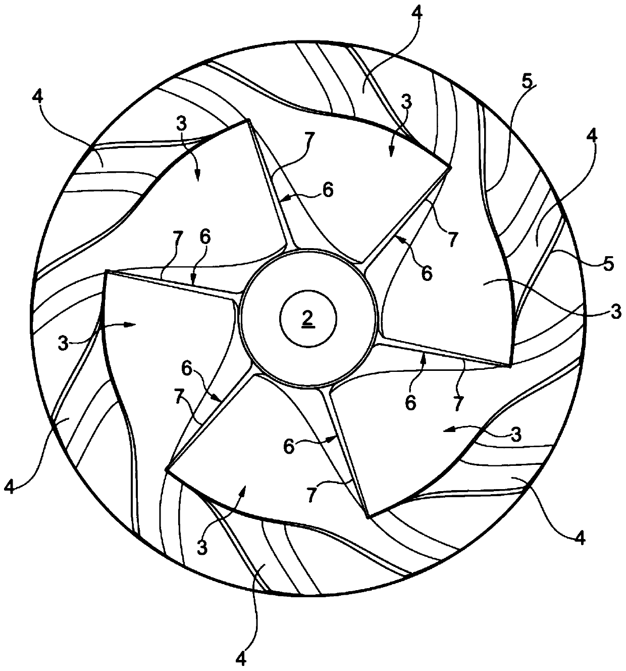
[0026] figure 1 The radial compressor wheel 1 shown in has a central shaft hole 2 by means of which the radial compressor wheel 1 can be arranged on the corresponding segment of the motor shaft, in the case of a turbocharger, Corresponding sections of the motor shaft connect the compressor wheel 1 to the turbine wheel in a rotatably fixed manner. During turbocharger operation, the turbine wheel is driven within the turbine housing by the exhaust gas flow of the internal combustion engine and then drives the radial compressor wheel 1 . In the illustrated embodiment, the compressor wheel 1 has six main blades 3 arranged in each case between auxiliary blades 4 . All blades 3 and 4 have a contoured edge 5 whose shape matches the internal contour of a compressor shroud, not shown, which receives the radial compressor wheel 1 . Thus, the contour of the edge 5 and the inner surface of the inner shroud match each other so that a "sealing gap" as close as possible is formed.

[0027...


PUM


Abstract

A compressor wheel for an internal combustion engine may include a plurality of blades which in a circumferential direction of the wheel are spaced from one another. The plurality of blades may respectively include an inflow edge which during operation are subject to an inflow of a compressible fluid substantially axially to the wheel axis. The plurality of blades may include a surface layer of locally distinct materials to adapt to locally distinct loads during operation.

Description

technical field [0001] The invention relates to a compressor wheel, in particular for a rotor of an exhaust gas turbocharger on an engine with internal combustion, said compressor wheel having blades spaced apart from each other in the circumferential direction of the wheel, in During operation of the compressor, said compressor wheel experiences an input of compressed fluid, in particular exhaust gases of the combustion process flowing in at low pressure from the engine side. [0002] The invention also relates to the manufacture of such a compressor wheel. Background technique [0003] In order to reduce emissions of nitrogen oxides, it is known to use internal combustion, especially in diesel engines, to provide exhaust gas recirculation, so that in each case a greater or lesser amount of exhaust gas is supplied to the combustion process of the engine. In this connection, high-pressure exhaust gas recirculation is known on the one hand, and low-pressure exhaust gas recir...

Claims


Application Information

Patent Timeline
Patent Type & Authority Patents(China)
IPC IPC(8): F04D29/30
CPCB23P15/006F01D5/046F01D5/288F05D2220/40Y10T29/49321Y10T29/49337
Inventor 克里斯蒂安娜·霍尔茨舒安德烈亚斯·哈斯马丁·施勒格克里斯蒂安娜·佩施克斯
Owner BMTS TECH SHANGHAI CO LTD
Why Eureka
Try Eureka