
Waveform optimization method for mimo sky-wave over-the-horizon radar

An over-the-horizon radar and waveform optimization technology, applied to radio wave measurement systems, instruments, etc., can solve problems such as low signal-to-noise ratio, no MIMO radar technology, and long coherence time

Inactive Publication Date: 2015-12-02
UNIV OF ELECTRONICS SCI & TECH OF CHINA
View PDF4 Cites 0 Cited by
  • Summary
  • Abstract
  • Description
  • Claims
  • Application Information

AI Technical Summary

Problems solved by technology

However, the existing studies are all based on a single-layer simple ionosphere model, which does not reflect the advantages of MIMO radar technology, because the signal-to-noise ratio of MIMO radar systems is always lower than that of phased-array radar systems with comparable configurations, that is to say, for To detect targets in a single direction, the performance of a phased array radar system will always be no worse than that of a MIMO radar
Although it can be compensated by thinking about accumulating time, as mentioned above, too long coherence time will bring more problems

Method used


Image

  • Waveform optimization method for mimo sky-wave over-the-horizon radar
  • Waveform optimization method for mimo sky-wave over-the-horizon radar
  • Waveform optimization method for mimo sky-wave over-the-horizon radar

Examples


Embodiment Construction

[0055] 1. Single-layer ionosphere signal model

[0056] Considering the MIMO linear array radar with M transmitting antennas and N receiving antennas, in order to simplify the model, it is assumed that the radar transceivers are co-located, and the number of receiving antennas and transmitting antennas is the same, that is, M=N. X=[x 1 ,x 2 ,...,x M ] are M orthogonal signal sets transmitted, where K is the number of signal samples transmitted by each antenna. broadcast response in In sky-wave over-the-horizon radar, the target is generally far away from the radar, and the target can be regarded as a point target, then h i,j Indicates the channel response factor between the i-th transmitting antenna and the j-th receiving antenna, which is the target scattering coefficient ε i,j , ionospheric reflection response factor δ i,j and ground and sea clutter interference φ i,j and the direction parameter η i,j product, i.e. h i,j =ε i,j ×δ i,j ×φ i,j ×η i,j ,i=1,2,....


PUM


Abstract

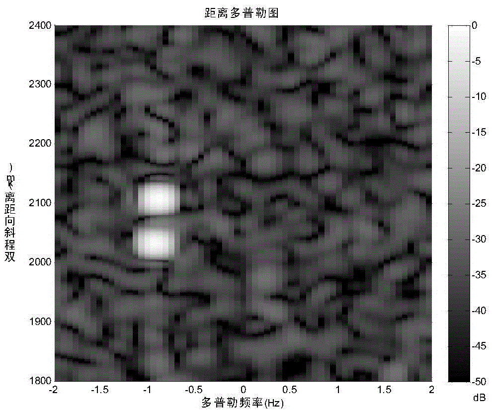
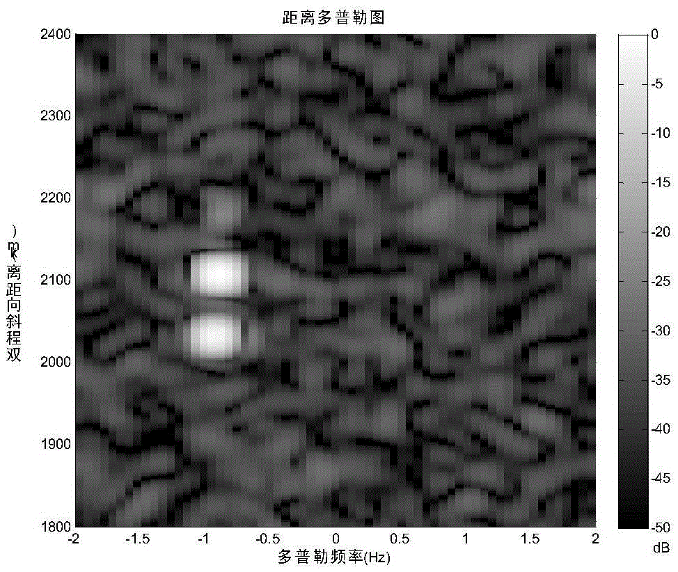
An MIMO (multiple input multiple output) radar technology can perform beam forming at both a transmitting end and a receiving end, particularly can emit narrow beams in different directions at the same time, and just can meet demands of a sky-wave over-the-horizon radar (OTHR) on multilayer ionospheric sounding and inhibition of relatively strong clutter. A two-ionized-layer structure is applied to an MIMO OTHR system, and aimed at a characteristic of relatively high clutter-noise ratio (CNR) caused by influence of sea clutter and ionized layers on the OTHR, a set of signal processing method is proposed and comprises adaptive optimization of a transmitted waveform with a two-step method of a mutual information theory. Simulation verification discovers that the method remarkably increases the target detection probability and resolution, so that the MIMO-OTHR can utilize multipath echoes to improve target detection and other system performances.

Description

technical field [0001] The invention mainly relates to the field of MIMO sky-wave over-the-horizon radar signal processing, including optimizing the transmission waveform from the feedback of the received signal. . Background technique [0002] The traditional sky-wave over-the-horizon radar mainly detects targets over 1,000 kilometers through the reflection of the ionosphere, works in the high-frequency band of 3-30MHZ, and has the characteristics of early warning and strong anti-stealth performance. However, due to the irregularity of the ionospheric electron concentration, a random disturbance is superimposed on the echo signal, resulting in the broadening of the clutter spectrum; in addition, the strong clutter interference from the sea surface and the ground is usually greater than the target signal, and the sky-wave over-the-horizon radar is slow in detecting Targets are often performance-limited. Sometimes in order to make the radar work effectively, it is necessary...

Claims


Application Information

Patent Timeline
Patent Type & Authority Patents(China)
IPC IPC(8): G01S7/02
CPCG01S7/023
Inventor 罗杨
Owner UNIV OF ELECTRONICS SCI & TECH OF CHINA
Learn More