Dry-type transformer for photovoltaic power generation and photovoltaic inversion system

A technology of dry-type transformers and photovoltaic power generation, which is applied in the field of power systems, can solve the problems of large heat generation of metal parts, and achieve the effects of avoiding circulating currents, reducing system costs, and low no-load current

CN104715906AActive Publication Date: 2015-06-17PEARL ELECTRIC
7 Cites 9 Cited by

Patent Information

Authority / Receiving Office
CN · China
Patent Type
Applications(China)
Current Assignee / Owner
Publication Date
2015-06-17

Smart Images

  • Figure 1
    Figure 1
  • Figure 2
    Figure 2
  • Figure 3
    Figure 3
Patent Text Reader

Abstract

The invention discloses a dry-type transformer for photovoltaic power generation and a photovoltaic inversion system. The dry-type transformer comprises main iron cores, low-voltage coils, leakage reactance iron cores and high-voltage coils; the upper / lower portions, protruding out of the low-voltage coils, of the main iron cores are provided with first clamping pieces respectively, and cross-core threaded rods penetrate through the first clamping pieces and the upper / lower portions of the main iron cores to fix the main iron cores; the upper / lower portions, protruding out of the high-voltage coils, of the leakage reactance iron cores are provided with second clamping pieces respectively, and side threaded rods penetrate through the second clamping pieces and the first clamping pieces to fix the leakage reactance iron cores and the main iron cores in the horizontal direction; the tops and the bottoms of the main iron cores and the leakage reactance iron cores are provided with top fixing plates and bottom fixing plates which stretch across the first clamping pieces and the second clamping pieces respectively, and the top fixing plates and the bottom fixing plates are connected through multiple vertical threaded rods to fix the main iron cores and the leakage reactance iron cores in the vertical direction; the side threaded rods, the top fixing plates and the bottom fixing plates are all coated with insulating layers, so that only a little metal connection is kept between the main iron cores and the leakage reactance iron cores, and the rest parts are all insulated.
Need to check novelty before this filing date? Find Prior Art

Description

technical field

[0001] The invention relates to the field of power systems, in particular to a dry-type transformer for photovoltaic power generation and a photovoltaic inverter system. Background technique

[0002] In the photovoltaic inverter system, the direct current generated by the solar cell, that is, the photovoltaic cell array, needs to be converted into alternating current through the inverter, and then transformed into the alternating current required for grid connection through the transformer. The output voltage of the inverter needs to be filtered by the LC filter circuit or LCL filter circuit composed of reactors and capacitors, and the output voltage waveform can meet the requirements of grid-connected power quality.

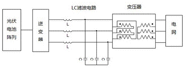
[0003] Traditional photovoltaic inverter systems such as figure 1 As shown, the photovoltaic cell array, inverter, LC filter circuit, transformer, and grid are connected in sequence.

[0004] The equipment composition in the traditional phot...

Examples

Embodiment Construction

[0034] The following will clearly and completely describe the technical solutions in the embodiments of the present invention with reference to the accompanying drawings in the embodiments of the present invention. Obviously, the described embodiments are only some, not all, embodiments of the present invention. Based on the embodiments of the present invention, all other embodiments obtained by persons of ordinary skill in the art without creative efforts fall within the protection scope of the present invention.

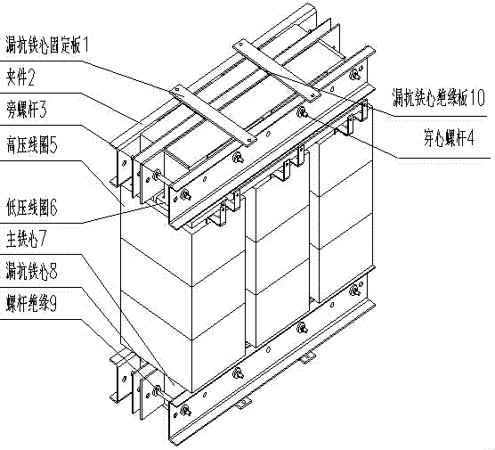
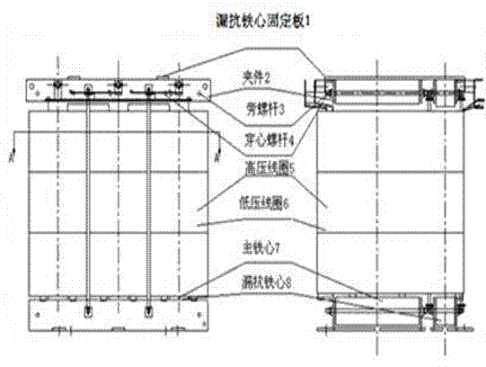
[0035] refer to Figure 2~Figure 3 The dry transformer for photovoltaic power generation provided by the present invention is mainly composed of a main iron core 7 , a low voltage coil 6 , a leakage reactance iron core 8 and a high voltage coil 5 .

[0036] Wherein, the main iron core 7 is formed by stacking at least one stacked layer, and the stacked layer is formed by stacking several iron core layers, and adjacent stacked layers are stacked in reverse dislocatio...