
Capacitor element winding device and capacitor element winding method

A winding device and capacitor technology, which is applied in the direction of winding capacitor machines, etc., can solve the problems of material waste, deterioration of the quality of capacitor elements, and reduction of the quality of capacitor elements.

Active Publication Date: 2015-06-17
SHENZHEN CHENGJIE INTELLIGENT EQUIP CO LTD
View PDF5 Cites 14 Cited by
  • Summary
  • Abstract
  • Description
  • Claims
  • Application Information

AI Technical Summary

Problems solved by technology

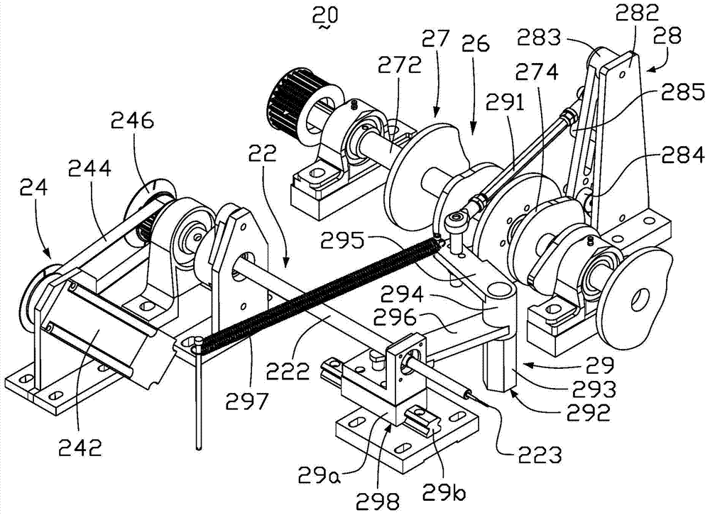
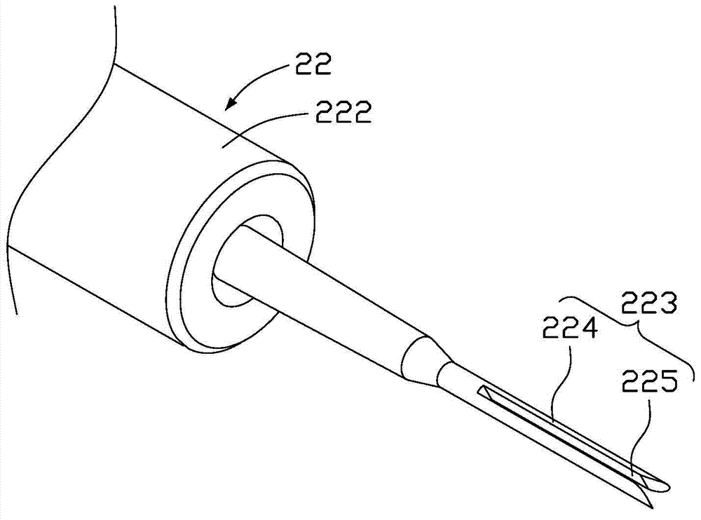
However, when the winding needle 223 of the capacitor element winding device 20 is extracted from the capacitor element, since the first winding needle arm 224 and the second winding needle arm 225 of the winding needle 223 are tightly wound together with the aluminum foil and the electrolytic paper, There will be relatively large frictional force between the first needle winding arm 224 and the second needle winding arm 225 and the aluminum foil and the electrolytic paper. 225 is easy to take out a part of the aluminum foil or electrolytic paper to deform the capacitor element, especially when making a element with a width of 20-30mm, the winding needle 223 of the capacitor element winding device 20 is easier to take out a part of the aluminum foil or electrolytic paper , so that the quality of the produced capacitor element is reduced, resulting in a waste of materials
Moreover, when the winding needle shaft 22 of the capacitor element winding device 20 rotates at a high speed, the first winding needle arm 224 and the second winding needle arm 225 will bend due to inertia, and then a gap will be generated between the aluminum foils of the capacitor element, reducing the capacity of the capacitor. Suzi's product quality

Method used


Image

  • Capacitor element winding device and capacitor element winding method
  • Capacitor element winding device and capacitor element winding method
  • Capacitor element winding device and capacitor element winding method

Examples


Embodiment Construction

[0026] In order to further explain the technical means and effects adopted by the present invention to achieve the intended purpose of the invention, the specific implementation of the capacitor element winding device and the capacitor element winding method proposed according to the present invention will be described below in conjunction with the accompanying drawings and preferred embodiments , structure, feature and effect thereof are described in detail as follows.

[0027] The aforementioned and other technical contents, features and effects of the present invention will be clearly presented in the following detailed description of preferred embodiments with reference to the drawings. Through the description of specific implementation methods, the technical means and effects of the present invention to achieve the intended purpose can be understood more deeply and specifically, but the attached drawings are only for reference and description, and are not used to explain t...


PUM


Abstract

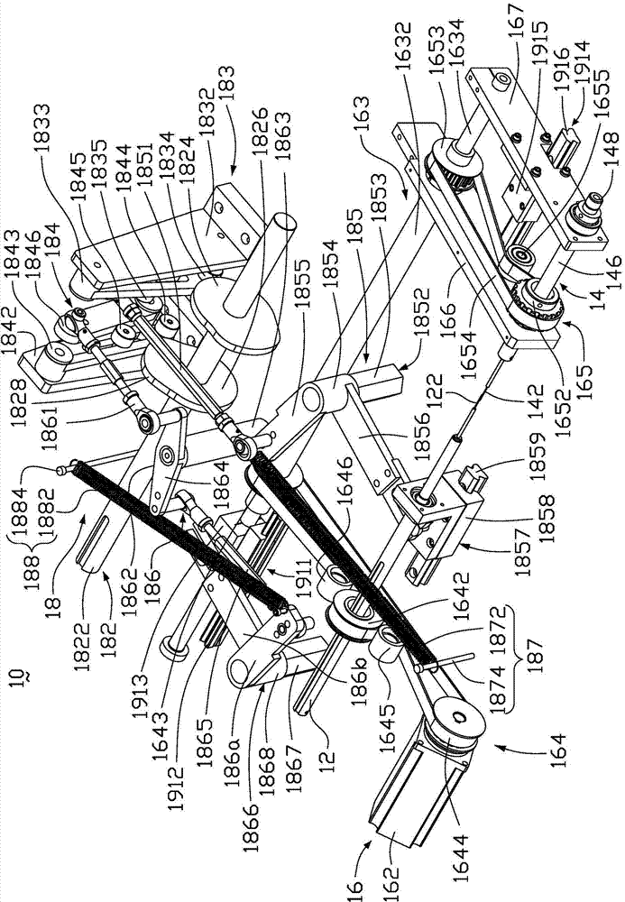
The invention discloses a capacitor element winding device which comprises a first rolling needle shaft, a second rolling needle shaft, a first driving mechanism and a second driving mechanism. The first rolling needle shaft and the second rolling needle shaft are coaxial and are oppositely arranged. The end, close to the second rolling needle shaft, of the first rolling needle shaft is provided with a first rolling needle facing the second rolling needle shaft, the end, close to the first rolling needle shaft, of the second rolling needle shaft is provided with a second rolling needle facing the first rolling needle shaft, and the first rolling needle and the second rolling needle get close to each other and are used for forming a capacitor element in a winding mode. The first driving mechanism drives the first rolling needle shaft and the second rolling needle shaft to rotate synchronously, and the second driving mechanism drives the first rolling needle shaft and the second rolling needle shaft to get close to each other or get away from each other. Capacitor element deformation caused when the capacitor element winding device conduct needle drawing can be avoided, gaps between aluminum foil of the capacitor element are reduced, the quality of a capacitor element product is improved, and material waste is reduced. The invention further relates to a capacitor element winding method.

Description

technical field [0001] The invention relates to a capacitor production device, in particular to a capacitor element winding device and a capacitor element winding method. Background technique [0002] A capacitor is a device that stores charge and is widely used in modern electronic and electrical equipment. The main structure of the capacitor includes a capacitor element formed by winding aluminum foil, electrolytic paper and a guide pin. [0003] figure 1 It is a structural schematic diagram of an existing capacitor element winding device. figure 2 It is a structural schematic diagram of a winding needle of an existing capacitor element winding device. Such as figure 1 and figure 2 As shown, the capacitor element winding device 20 includes a needle winding shaft 22 , a first driving mechanism 24 and a second driving mechanism 26 . The needle winding shaft 22 includes a needle winding rod 222 and a winding needle 223 connected to the end of the needle winding rod 22...

Claims


Application Information

Patent Timeline
IPC IPC(8): H01G13/02
Inventor 谭国彪刘云宗勇
Owner SHENZHEN CHENGJIE INTELLIGENT EQUIP CO LTD
Learn More