Electroacoustic transducer, manufacturing method thereof, and electronic device using electroacoustic transducer

A technology of electroacoustic transducer and manufacturing method, applied in transducer circuits, piezoelectric/electrostrictive transducers, sensors, etc., to achieve the effect of high-efficiency oscillation

Inactive Publication Date: 2017-08-25
NEC CORP
View PDF2 Cites 0 Cited by
  • Summary
  • Abstract
  • Description
  • Claims
  • Application Information

AI Technical Summary

Problems solved by technology

However, it is difficult in principle to miniaturize electrokinetic electroacoustic transducers

Method used


Image

  • Electroacoustic transducer, manufacturing method thereof, and electronic device using electroacoustic transducer
  • Electroacoustic transducer, manufacturing method thereof, and electronic device using electroacoustic transducer
  • Electroacoustic transducer, manufacturing method thereof, and electronic device using electroacoustic transducer

Examples


Embodiment 1

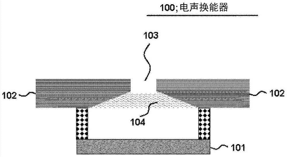
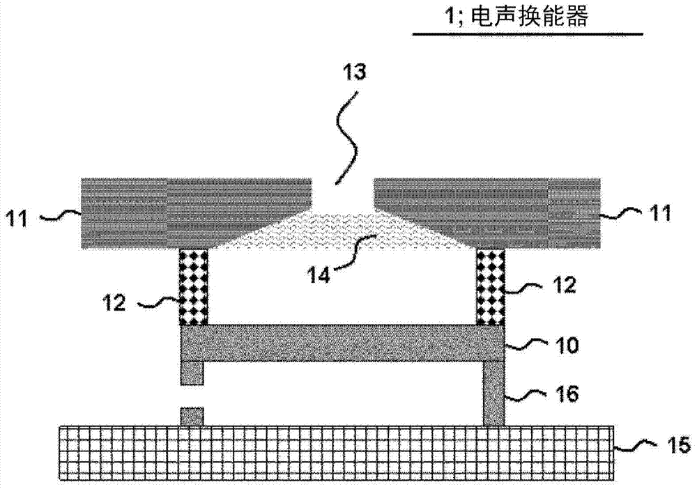
[0040] The first exemplary embodiment will be described in more detail with reference to the drawings.

[0041] figure 2 is a sectional side view showing an example of the electroacoustic transducer 1 related to the present exemplary embodiment. Also, for brevity, figure 2 Only components related to the electroacoustic transducer 1 related to the present exemplary embodiment are shown.

[0042] The electro-acoustic transducer 1 is arranged inside the casing 11 . For example, the electroacoustic transducer 1 is used as a speaker device. The speaker device may be a parametric speaker. In the case of using the electroacoustic transducer 1 as a parametric speaker, it is preferable that the piezoelectric vibrator transmits ultrasonic waves having a frequency greater than 20 kHz. In this case, a parametric speaker demodulates the ultrasonic waves into an audible sound as a carrier wave. Specifically, first, the parametric speaker emits modulated ultrasonic waves into the atm...

Embodiment 2

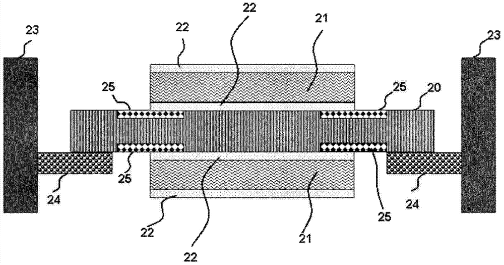
[0062] A second exemplary embodiment will be described in more detail with reference to the drawings.

[0063] In the second exemplary embodiment, the electroacoustic transducers 1 related to the first exemplary embodiment are arranged side by side on a plane. Note that descriptions overlapping with the first exemplary embodiment are omitted in the description of the present exemplary embodiment. In addition, the same symbols are given to the same elements as those in the first exemplary embodiment, and descriptions of these same elements will be omitted in the description of the present exemplary embodiment.

[0064] Figure 4 is a side view of a structural example of the electro-acoustic transducer 1a of the present exemplary embodiment.

[0065] Each piezoelectric vibrator 10 is joined to the housing 11 via the joining member 12 . Furthermore, each piezoelectric vibrator 10 is bonded to the substrate 15 via the holding member 16 . Also, a frustum-shaped cutout in the ho...


PUM


Abstract

The present invention is advantageous for efficiently transmitting high-directional ultrasonic waves. An electroacoustic transducer comprising: a piezoelectric vibrator; a casing disposed at a predetermined space from the piezoelectric vibrator, and including a frustum-shaped cutout in an inner wall of the casing; and a sound absorbing material fitted in the cutout; wherein , an acoustic hole is formed in the case in front of the piezoelectric vibrator along the oscillation direction of the piezoelectric vibrator; and the slit is formed in the case so that the hole diameter of the sound path faces along the oscillation direction of the piezoelectric vibrator reduced at the front end.

Description

[0001] This application is based on and claims the benefit of priority from Japanese Patent Application No. 2012-227920 filed on October 15, 2012, the entire disclosure of which is hereby incorporated by reference. technical field [0002] The present invention relates to an electroacoustic transducer, a manufacturing method of the electroacoustic transducer and electronic equipment using the electroacoustic transducer. Background technique [0003] In recent years, parametric loudspeakers having high directivity to radiate sound to a person at a specific position have attracted attention. It is desirable to mount a parametric speaker on an electronic device, such as a mobile phone, and to use the parametric speaker to propagate an acoustic signal around a user. [0004] Here, when the parametric speaker is mounted on an electronic device such as a mobile phone, it is desired to miniaturize the parametric speaker. In principle, however, it is difficult to miniaturize an ele...

Claims


Application Information

Patent Timeline
Patent Type & Authority Patents(China)
IPC IPC(8): H04R17/00H04R3/00H04R31/00
CPCH04R31/00H04R1/403H04R2217/03H04R1/40Y10T29/42H04R17/00
Inventor 大西康晴
Owner NEC CORP
Why Eureka
Try Eureka