A Piezoelectric Wind Energy Harvester with a Resonant Cavity

A collector and resonant cavity technology, applied in the field of micro energy recovery, can solve the problems of low energy conversion efficiency, narrow working wind speed range, high critical starting wind speed, etc., and achieve the effect of simple structure, wide working wind speed range and low critical starting wind speed

Active Publication Date: 2019-01-11
SHANGHAI UNIV
View PDF6 Cites 0 Cited by
  • Summary
  • Abstract
  • Description
  • Claims
  • Application Information

AI Technical Summary

Problems solved by technology

[0005] The purpose of the present invention is to provide a piezoelectric wind energy collector with a resonant cavity to solve the problems of low energy conversion efficiency, high critical starting wind speed, narrow working wind speed range, and low output power of the prior art miniature wind energy collectors.

Method used


Image

  • A Piezoelectric Wind Energy Harvester with a Resonant Cavity
  • A Piezoelectric Wind Energy Harvester with a Resonant Cavity
  • A Piezoelectric Wind Energy Harvester with a Resonant Cavity

Examples


Embodiment Construction

[0016] The present invention will be further described with reference to the drawings and specific embodiments below.

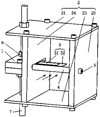
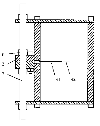
[0017] Such as Figure 1 to Figure 3 As shown, a piezoelectric wind energy collector with a resonant cavity includes a clamping plate 1, a rectangular cavity 2, a piezoelectric vibrator 3, and a column 4, and two clamping plates 1 fix one end of the piezoelectric vibrator 3 by bolts , the other end of the piezoelectric vibrator 3 extends into the rectangular cavity 2 in a free state; the column 4 is fixed on the rectangular cavity 2 by screws 5, and is located in front of the piezoelectric vibrator 3, close to the rectangular cavity 2 At one end of the tuyere, the rectangular cavity 2 is fixed on a long stud 7 through a nut 6 .

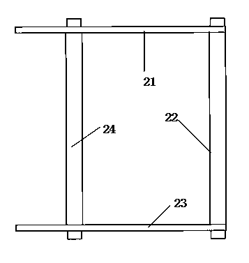
[0018] Described rectangular cavity 2 is formed by upper plate 21, lower plate 23, right side plate 22, and left side plate 24 is connected by hexagon socket head cap screw, and it has an air inlet and an air outlet, and described l...


PUM


Abstract

The invention relates to a piezoelectric wind energy collector with a resonant cavity. The collector comprises two clamping plates, a rectangular cavity, a piezoelectric oscillator, and a column. The two clamping plates fix one end of the piezoelectric oscillator through bolts, and the other end of the piezoelectric oscillator extends into the rectangular cavity and is in a free state. The column is fixed on the rectangular cavity by a screw. The column is in front of the piezoelectric oscillator and near the air inlet end of the rectangular cavity. The rectangular cavity is fixed on a long stud by a nut. The resonant cavity can effectively change the near field air flow characteristics of the piezoelectric oscillator, so that the piezoelectric oscillator can generate high-efficiency oscillation, and the efficiency of wind energy collection is improved. The collector is low in critical starting wind speed, wide in working wind speed range, simple in structure, and easy for miniaturization.

Description

technical field [0001] The invention belongs to the field of miniature energy recovery, in particular to a piezoelectric wind energy collector with a resonant cavity. Background technique [0002] With the excessive development and utilization of fossil energy such as petroleum and coal, the quantity of these non-renewable resources is continuously decreasing. How to maintain the supply of energy and how to protect the living environment from pollution are urgent problems that people need to solve. Therefore, the development and utilization of renewable resources has become the focus of governments, scientific research institutions and enterprises. [0003] The micro-energy harvester converts the micro-energy (such as solar energy, wind energy, thermal energy, electromagnetic wave, light, human body and mechanical vibration energy, etc.) existing in the surrounding environment into electrical energy, and then directly supplies power to microelectronic devices through the col...

Claims


Application Information

Patent Timeline
Patent Type & Authority Patents(China)
IPC IPC(8): H02N2/18
CPCH02N2/185
Inventor 张健滔张佳舒畅吴松
Owner SHANGHAI UNIV
Why Eureka
Try Eureka