Flip type drain valve and drain valve control method

A control method and drainage valve technology, which is applied in water supply devices, flushing equipment with water tanks, buildings, etc., can solve the problems of waste of water resources and non-adjustable drainage, and achieve excellent results

Active Publication Date: 2015-07-01
ECO XIAMEN TECH INC
View PDF6 Cites 5 Cited by
  • Summary
  • Abstract
  • Description
  • Claims
  • Application Information

AI Technical Summary

Problems solved by technology

However, most of the drain valves with pilot valve structure on the market only have a single-row fun

Method used


Image

  • Flip type drain valve and drain valve control method
  • Flip type drain valve and drain valve control method
  • Flip type drain valve and drain valve control method

Examples


Embodiment

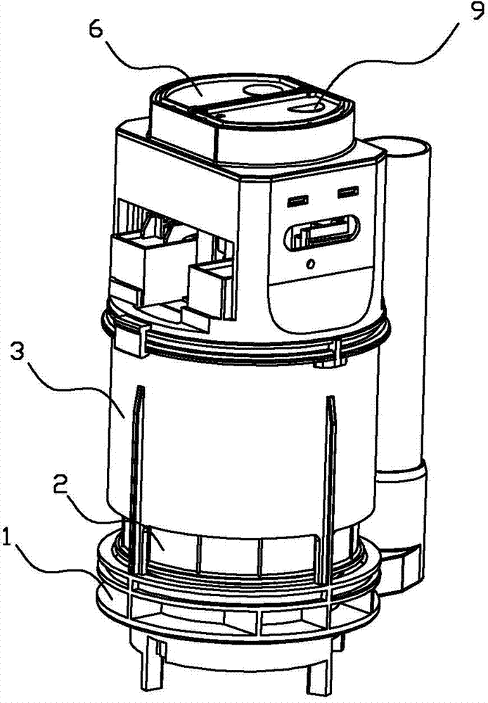
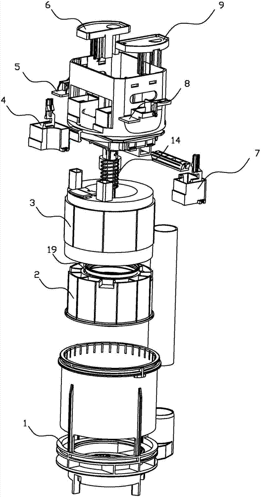
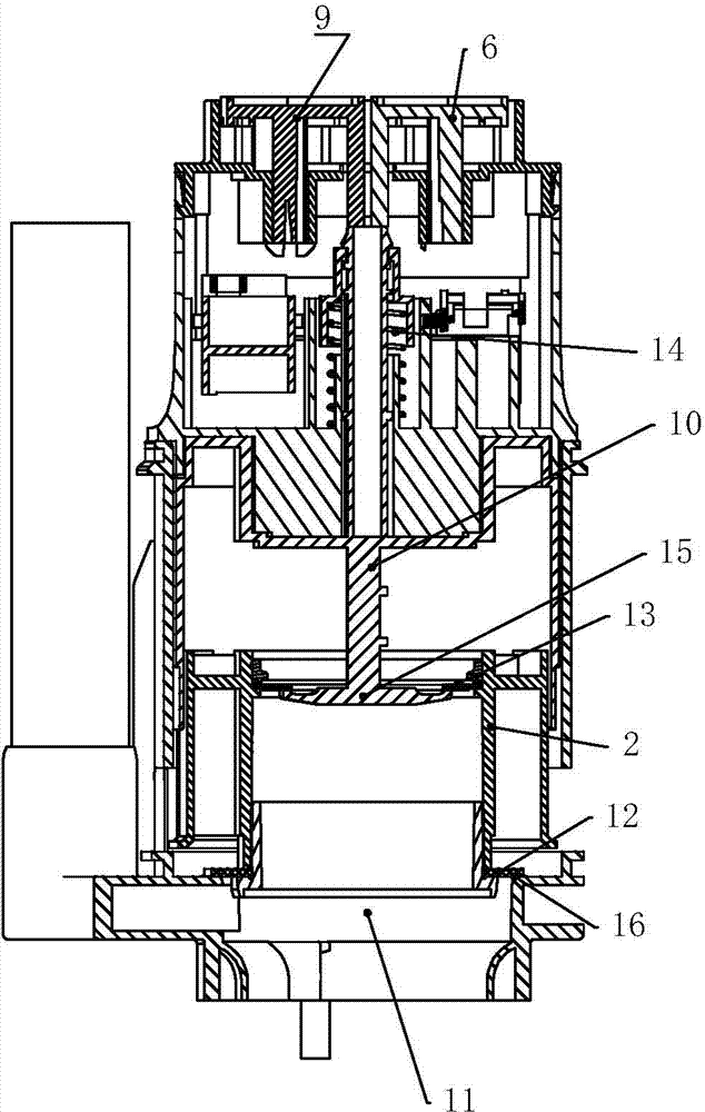
[0043] Such as figure 1 , figure 2 As shown, the drain valve includes a base 1, a water-stop buoy 2, an outer cover 3, a full row of buoys 4, a full row of ventilation valves 5, a full row of buttons 6, a full row of chambers 20, a half row of buoys 7, a half row of ventilation valves 8, A half row of buttons 9, a half row of chambers, a drain rod 10, a drain port 11, a drain seal 12, a water stop buoy seal 13, and a return spring 14.

[0044] This embodiment takes the full row function as an example. After pressing the button 6 of the whole row, the water in the cavity on the upper surface of the water-stop buoy 2 flows out first, and because the gap around the cavity is small, the amount of water supplied into the cavity is very small, so that the water pressure in the cavity decreases rapidly, and the water is stopped. The upward hydraulic pressure of the buoy 2 is greater than the sum of the self-weight of the water-stop buoy 2 and the downward hydraulic pressure, so th...


PUM


Abstract

The invention relates to a flip type drain valve. The flip type drain valve comprises a water-stop floating barrel, an outer cover, a drain component and a ventilating check valve. The water-stop floating barrel is movably connected to the outer cover. The drain component penetrates the water-stop floating barrel to be movably connected to the outer cover. A cavity is formed by the water-stop floating barrel, the outer cover and the ventilating check valve in a surrounding manner. Negative pressure in the cavity is controlled through control of opening and closing of the ventilating check valve, and descending and ascending of the water-stop floating barrel is further controlled to achieve water drainage of the drain valve. A drain valve control method includes that the cavity is formed by the water-stop floating barrel, the outer cover and the ventilating check valve in a surrounding manner, the negative pressure is formed in the cavity after water in the cavity is drained, and the water-stop floating barrel is controlled to ascend to open the drain valve; the ventilating check valve is opened to release the negative pressure in the cavity, and the water-stop floating barrel descends under the acting force of dead weight to close the drain valve. The drain valve can drain water by flipping, and control of water drainage volume is reliable and simple.

Description

technical field [0001] The present invention relates to the technical field of a drain valve, and more specifically relates to a lightly pressed drain valve and a control method for the drain valve. Background technique [0002] Most of the drain valves traditionally used in toilet water tanks adopt a lever mechanical structure, which requires a lot of effort to press the button when in use. The lever mechanism is moved to lift the water sealing sheet to realize drainage, so this type of drain valve is laborious to use and inconvenient to operate. [0003] The drain valve with a pilot valve structure is a light-touch drain valve. When it is used, it can be flushed and drained only by applying a slight pressing force, so it has the advantages of easy operation and convenient use. However, most of the drain valves with a pilot valve structure currently on the market only have a single-row function and the displacement cannot be adjusted, so that water resources will be wasted...

Claims


Application Information

Patent Timeline
IPC IPC(8): E03D1/35
CPCE03D1/35
Inventor 谢文清
Owner ECO XIAMEN TECH INC
Why Eureka
Try Eureka