Time domain broadband harmonic domain beamformer and beamforming method for circular array

A harmonic domain and former technology, applied in the field of time-domain broadband harmonic domain beamformer and beamforming, can solve the problem of unsuitable real-time signal processing

Active Publication Date: 2018-03-23
浙江望海潮科技有限公司
View PDF4 Cites 0 Cited by
  • Summary
  • Abstract
  • Description
  • Claims
  • Application Information

AI Technical Summary

Problems solved by technology

[0006] The purpose of the present invention is to provide a time-domain broadband harmonic domain beam for circular arrays in order to solve the technical problem that existing broadband harmonic domain beamformers and frequency domain processing methods are not suitable for real-time signal processing of circular arrays Formers and Beamforming Methods

Method used


Image

  • Time domain broadband harmonic domain beamformer and beamforming method for circular array
  • Time domain broadband harmonic domain beamformer and beamforming method for circular array
  • Time domain broadband harmonic domain beamformer and beamforming method for circular array

Examples


Embodiment Construction

[0067] The time-domain broadband harmonic domain beamformer and beamforming method for circular arrays of the present invention will be described in detail below with reference to the accompanying drawings and embodiments.

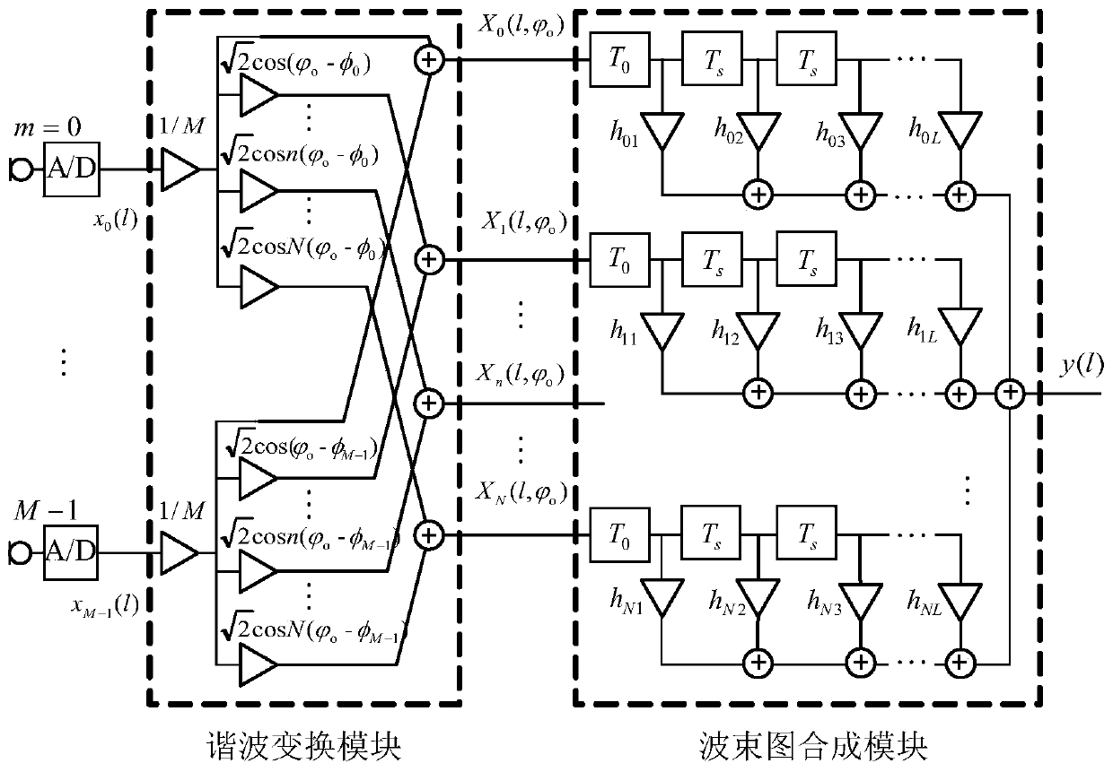
[0068] Such as figure 1 As shown, a kind of time-domain broadband harmonic domain beamformer for circular array of the present invention, described beamformer comprises: Harmonic conversion module and beam pattern synthesis module; Described harmonic conversion module, uses It is used to sample the data received by the ring sensor array and perform ring harmonic transformation to obtain ring harmonic domain data; the beam pattern synthesis module is a beam pattern synthesis module based on an FIR filter, which is used to convert the harmonic transformation module Each order circular ring harmonic domain data of output and the coefficient of FIR filter carry out convolution processing respectively, then each FIR filter output summation, obtain time domain b...


PUM


Abstract

The present invention provides a time-domain broadband harmonic domain beamformer and a beamforming method for a circular array. The beamformer includes: a harmonic transformation module and a beam pattern synthesis module. The data received by the array element is sampled and passed through the harmonic transformation module, and then the ring harmonic domain data of each order output by the harmonic transformation module are summed through the corresponding FIR filter to obtain the beam output. Using this beamforming method, the obtained time-domain broadband harmonic domain beam can take into account multiple performance indicators of the beamformer, and can appropriately reduce the number of performance indicators that need to be considered, that is, properly select the cost function and constraint function according to actual needs, Different constraint combinations constitute different beam optimization criteria, so it has strong practicability and wide application adaptability; and the number of channels M in the classical array element domain beamforming is reduced to N+ in the harmonic domain processing of the present invention 1 (where M>2N), reducing the amount of calculation.

Description

technical field [0001] The invention relates to the field of array signal processing, in particular to a time-domain broadband harmonic domain beamformer and a beamforming method for a circular array. Background technique [0002] Beamforming processing is widely used in the fields of microphone arrays, sonar, radar, and wireless communications. The general array element domain beamforming process is as follows: a spatially distributed sensor array is used to collect data, and then the collected array data is linearly weighted and combined A scalar beam output is obtained after processing, which is done by the beamformer. By designing the weighting coefficients, the response of the array receiving system is directional, so the beamformer can be used for spatial filtering to improve the signal-to-noise ratio. [0003] In the published document of the existing invention patent No. ZL 201010186643.1, a time-domain broadband beamformer implementation method for spherical array ...

Claims


Application Information

Patent Timeline
Patent Type & Authority Patents(China)
IPC IPC(8): H04R3/00
Inventor 鄢社锋马晓川侯朝焕
Owner 浙江望海潮科技有限公司
Why Eureka
Try Eureka