Terminal extraction jig

A terminal and jig technology, which is applied in the assembly/disassembly of contacts, fixing/insulating contact members, electrical components, etc., can solve the problem of unstable insertion posture of the terminal pull-out jig, and the locking of the lance and the terminal metal piece. Eliminate problems such as labor and work, and achieve the effect of simple structure

Inactive Publication Date: 2015-07-29
YAZAKI CORP
View PDF1 Cites 5 Cited by
  • Summary
  • Abstract
  • Description
  • Claims
  • Application Information

AI Technical Summary

Problems solved by technology

Therefore, in the case of an operator who is not skilled in terminal extraction work, there are problems in that the insertion posture of the terminal extraction jig is unstable, and it takes time and effort to disengage the locking lance and the terminal metal fitting.

Method used


Image

  • Terminal extraction jig
  • Terminal extraction jig
  • Terminal extraction jig

Examples


no. 1 Embodiment approach >

[0035] use figure 1 -5 The first embodiment will be described.

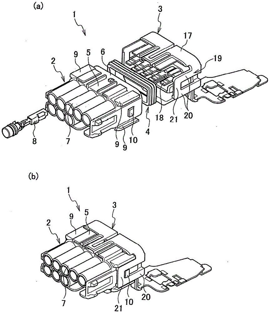
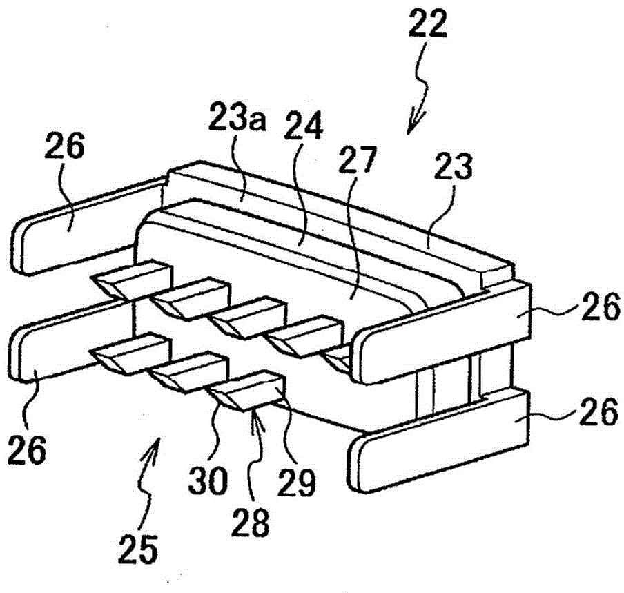
[0036] The terminal extraction jig 22 of the first embodiment is used for figure 1 The illustrated connector 1 can release the engagement state between the terminal metal piece 8 accommodated in the terminal accommodation chamber 11 of the connector 1 and the locking lance 12 engaged with the terminal metal piece 8, and the terminal metal piece The member 8 is pulled out from the terminal accommodating chamber 11.

[0037] Such as figure 1 As shown, the connector 1 includes: a first connector 2; a second connector 3 as a counterpart connector, which is fitted with the first connector 2; and a waterproof gasket 4, which is clamped on the first connection Between the connector 2 and the second connector 3, waterproofing is performed.

[0038] The first connector 2 includes: a connector housing 5; a cover 6 provided on one end side of the connector housing 5 and fitted to the second connector 3; and a wire lead-...

no. 2 Embodiment approach >

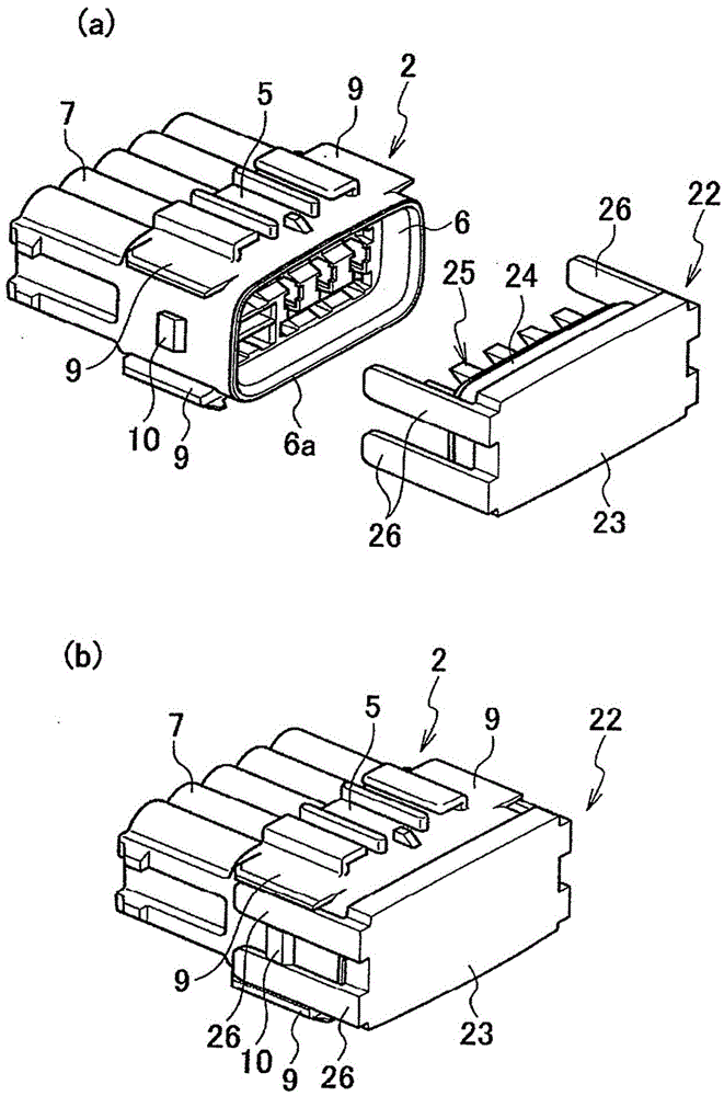
[0054] Next, explain Image 6 (a), 6(b), and 2nd Embodiment shown in 7. In the second embodiment, for the same components as those of the first embodiment, in Image 6 (a), 6(b), and 7 are shown with the same reference numerals as those of the first embodiment, and overlapping descriptions are omitted.

[0055] In the terminal extraction jig 33 of the second embodiment, the leading ends of the guide pieces 26, 26 are connected by the connection holding portion 31, and the inside surrounded by the guide pieces 26, 26, and the connection holding portion 31 is formed as a rectangular through hole. .

[0056] Such as Image 6 As shown in (a) and 6(b), the connection holding part 31 is provided between the ribs 9 and 9 of the connector housing 5, and like the connection holding part 21 of the second connector 3, it is fitted with the connector housing 5. The retaining protrusion 10 is snapped together. When the connection holding portion 31 is engaged with the fitting holding ...


PUM


Abstract

A terminal extraction jig (22) is provided with: a base wall section (23) which is greater than the outer diameter of the hood section (6) of a connector housing (5) into which a counter-connector (3) can be fitted; a fitting base section (24) which is provided to the base wall section (23) and which fits into the hood section (6); unlocking protrusions (28) which protrude from the fitting base section (24) and which can unlock the engagement between locking lances (12) and terminal elements (8) while the fitting base section (24) is fitted in the hood section (6) of the connector housing (5); and a guide section (26) which is provided to the base wall section (23), engages with a rib (9) for guiding the fitting between the connector housing (5) and the counter-connector (3), and guides the fitting of the fitting base section (24) into the hood section (6).

Description

technical field [0001] The present invention relates to a terminal pulling jig for releasing the engaged state of a locking lance in a terminal accommodation chamber of a connector housing and a terminal metal piece and pulling out the terminal metal piece from the terminal accommodation chamber. Background technique [0002] Usually, the terminal fitting inserted into the terminal accommodation chamber of the connector housing is prevented from coming out of the terminal accommodation chamber by engaging with a locking lance provided in the terminal accommodation chamber. In order to pull out the terminal fitting from the terminal accommodation chamber, the engagement of the locking lance and the terminal fitting is released and the terminal fitting is pulled out from the terminal accommodation chamber. An insertion hole is provided on the connector housing close to the terminal accommodating chamber. When releasing the engagement between the locking lance and the terminal ...

Claims


Application Information

Patent Timeline
Patent Type & Authority Applications(China)
IPC IPC(8): H01R43/22H01R13/42
CPCH01R43/22H01R13/4223
Inventor 中岛隆人山崎沙织永野雅生斋藤雅幸
Owner YAZAKI CORP
Why Eureka
Try Eureka