Non-hyperbolic velocity scanning and dynamic correction method

A speed scanning, non-hyperbolic technology, applied in the field of geophysical exploration, can solve problems such as difficult to obtain

Inactive Publication Date: 2015-08-12
夏正元
View PDF5 Cites 4 Cited by
  • Summary
  • Abstract
  • Description
  • Claims
  • Application Information

AI Technical Summary

Problems solved by technology

For complex surface multi-layer velocity models, use the ray tracing method to obtain time-distance curves, but an accurate str

Method used


Image

  • Non-hyperbolic velocity scanning and dynamic correction method
  • Non-hyperbolic velocity scanning and dynamic correction method
  • Non-hyperbolic velocity scanning and dynamic correction method

Examples


Embodiment 1

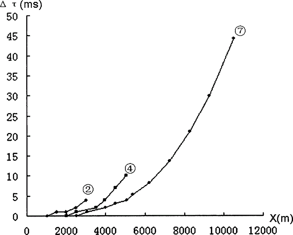
[0038] With the method of velocity scanning and dynamic correction of the present invention, model A is a horizontal layered velocity model in an actual area, with 7 layers in total: the thickness of the first layer is 600m, and the seismic wave velocity is 2800m / s; the thickness of the second layer is 450m, and the seismic wave The velocity is 3200m / s; the thickness of the third layer is 850m, and the seismic wave velocity is 3500m / s; the thickness of the fourth layer is 400m, and the seismic wave velocity is 4000m / s; the thickness of the fifth layer is 400m, and the seismic wave velocity is 4100m / s; the thickness of the sixth layer is 650m , the seismic wave velocity is 4450m / s; the thickness of the seventh layer is 500m, and the seismic wave velocity is 4300m / s. The obtained Δτ(x) time difference curves of the 2nd, 4th, and 7th floors ( image 3 , Figure 4 ), the more layers of the model, the greater the time difference Δτ, and the larger the offset x, the greater the tim...

Embodiment 2

[0040] Using the method of velocity scanning and dynamic correction of the present invention, Δτ is calculated for the layer velocity model of model B. Model B is a horizontal layer velocity model with 7 layers in total. Model B and model A only change the velocity of the fifth layer. , the thickness of the fifth layer is 400m, and the seismic wave velocity is 6000m / s. The relationship diagram between the obtained time difference curve Δτ(x) and x / h of the seventh floor ( Figure 5 ), when the ratio of offset to formation depth (x / h) is 1.5, the Δτ time difference of the seventh layer of model B reaches 20ms, and the hyperbolic method cannot be used for velocity scanning and dynamic correction. The Δτ of the seventh layer of model B The time difference is up to 8ms, and it is basically feasible to use the hyperbolic method for speed scanning and dynamic correction. For areas where there are high-speed formations, such as carbonate rock areas, the method of the invention is us...

Embodiment 3

[0042] Using the method of the present invention to obtain the stacking velocity error caused by the large offset distance, the hyperbolic equation velocity scan is used to obtain the stacking velocity in a certain area. According to the actual model A and the maximum offset distance, for the fourth layer, the processing method used The maximum offset distance is 4500m, and its Δτ time difference reaches 7ms. The maximum velocity error ΔVm calculated by the method of the present invention is 24m / s. For the 7th floor, the maximum offset distance adopted during processing is 6200m, and the Δτ time difference reaches 8ms. The calculated maximum velocity error ΔVm is 29m / s, and the stacked velocity error ΔVe caused by the large offset is estimated, and ΔVe is half of ΔVm; through the application of this method, high-precision formation velocity information in this area can be obtained.


PUM


Abstract

The invention provides a non-hyperbolic velocity scanning and dynamic correction method and a method of calculating stacking velocity errors caused by big offset distance in the geophysical prospecting technology. By adopting a time-difference analysis between a radial time curve of a seismic layer velocity model forward modeling and a stacking velocity speed Va time hyperbola, a new non-hyperbolic equation can be provided for the velocity scanning and the dynamic correction, and then the more accurate stacking velocity and dynamic correction time difference can be acquired. For a horizontally layered medium, the error can be caused by using the hyperbolic equation for the scanning of the stacking velocity and the root-mean-square velocity by adopting the time difference analysis between the radial time curve and the time hyperbola of the root-mean-square velocity, and then the method of estimating the stacking velocity error caused by the large offset distance can be provided. The method is used in a plurality of areas, and the good effect can be achieved.

Description

technical field [0001] The invention relates to geophysical exploration technology, belongs to the technical category of seismic data processing and interpretation, and is a method for stacking velocity analysis and dynamic correction technical background [0002] In seismic exploration, seismic wave velocity is a very important parameter, especially seismic data processing, seismic data interpretation, migration imaging, AVO oil and gas detection, etc. all require seismic wave velocity parameters. In seismic data processing, a large amount of velocity spectrum data is obtained. The stacking velocity explained by the processor is mainly used for dynamic correction, which can level the reflected wave event of the CMP gather. However, when the offset is large, the CMP trace The reflected wave event of the set is uneven, which will affect the superposition effect and the accuracy of superposition velocity calculation. Stacking velocity scanning and dynamic correction methods u...

Claims


Application Information

Patent Timeline
IPC IPC(8): G01V1/30G01V1/36
Inventor 夏正元夏艺苟堡铭黄研
Owner 夏正元
Why Eureka
Try Eureka