
Timing position change device

A displacement device and aging technology, applied in the direction of hoisting device, hoisting device, etc., can solve the problems of inability to guarantee the accuracy, many auxiliary equipment, and many manpower, etc., and achieve the effect of convenient appearance inspection.

Active Publication Date: 2015-09-09
成都润博科技有限公司
View PDF7 Cites 0 Cited by
  • Summary
  • Abstract
  • Description
  • Claims
  • Application Information

AI Technical Summary

Problems solved by technology

There are many auxiliary equipment and manpower, the accuracy cannot be guaranteed, and there are major safety hazards

Method used


Image

  • Timing position change device
  • Timing position change device
  • Timing position change device

Examples


Embodiment Construction

[0024] In order to make the technical means, creative features, goals and effects achieved by the present invention easy to understand, the present invention will be further described below in conjunction with specific embodiments.

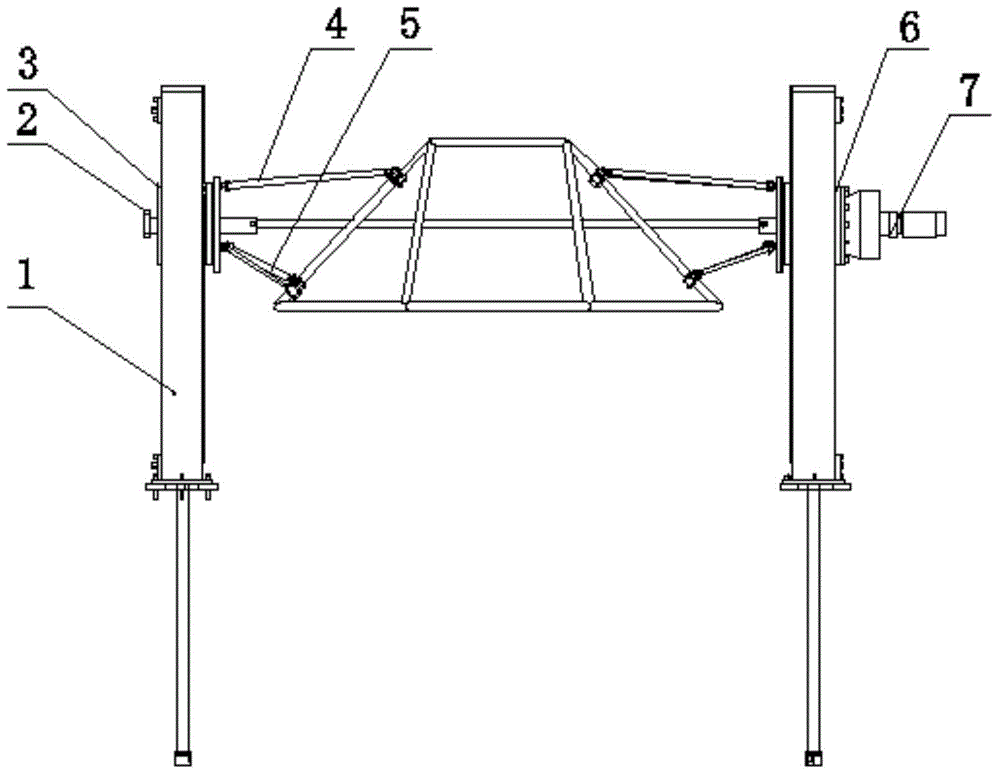
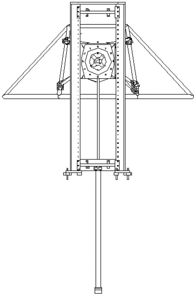
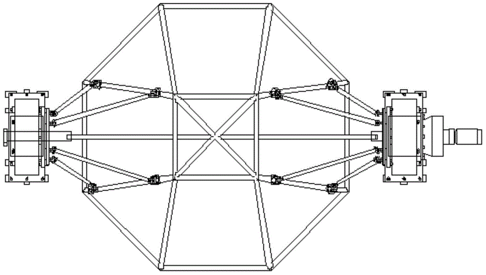
[0025] refer to Figure 1 to Figure 9 As shown, an aging displacement device of the present invention includes a door frame assembly 1 arranged on both sides, a left support seat assembly 3 and a right support seat assembly 6 arranged on the door frame assembly 1, and a through The linkage shaft assembly 2 of the left support seat assembly 3 and the right support seat assembly 6, and the long connecting rod assembly 4 and the short connecting rod assembly 5 connected with the left support seat assembly 3 and the right support seat assembly 6 , and the geared motor 7 connected with the right support base assembly 6.

[0026] The gantry assembly 1 includes a gantry welding plate 11, a limit tooling welding plate 12 arranged at the bottom of the gan...


PUM


Abstract

The invention discloses a timing position change device. The timing position change device comprises portal assemblies arranged on the two sides, a left support assembly, a right support assembly, a linkage shaft assembly, a long connecting rod assembly, a short connecting rod assembly, and a speed reduction motor, wherein the left support assembly and the right support assembly are arranged on the portal assemblies, the linkage shaft assembly penetrates through the left support assembly and the right support assembly, the long connecting rod assembly and the short connecting rod assembly are connected with the left support assembly and the right support assembly, and the speed reduction motor is connected with the right support assembly. The timing position change device is simple in structure, can quickly clamp workpieces, overturn products and change the positions of products safely and rapidly, and production efficiency is greatly improved.

Description

technical field [0001] The invention relates to an aging displacement device. Background technique [0002] The aging displacement device is suitable for the aging equipment of castings, forgings, welding parts, grinding tools and machined parts made of carbon structural steel, low alloy steel, stainless steel, cast iron, non-ferrous metals (copper, aluminum, titanium and their alloys) In the process of use, it is often encountered that large workpieces need to be flipped or displaced. The traditional method is to use special equipment, forklifts and multiple manpower to solve the problem. There are a lot of auxiliary equipment, a lot of manpower, the accuracy cannot be guaranteed, and there are major safety hazards. Contents of the invention [0003] The technical problem to be solved by the present invention is to provide a time-sensitive displacement device with a simple structure, which can quickly realize the clamping of the workpiece, safely and quickly flip and di...

Claims


Application Information

Patent Timeline
Patent Type & Authority Applications(China)
IPC IPC(8): B66F19/00
CPCB66F19/00
Inventor 周明军黄东姚中伟张小兵陈明
Owner 成都润博科技有限公司
Learn More