Error correction method of flying probe tester

A technology of flying probe testing machine and calibration method, which is applied in the direction of electronic circuit testing, etc., can solve the problems of poor accuracy of flying probe testing, and achieve the effects of fast process, improved calibration speed and high efficiency

Active Publication Date: 2015-09-16
JOINT STARS TECH
View PDF8 Cites 26 Cited by
  • Summary
  • Abstract
  • Description
  • Claims
  • Application Information

AI Technical Summary

Problems solved by technology

[0005] For this reason, the technical problem to be solved by the present invention is that the flying probe testing accuracy of the existing flying probe testing machine is relatively poor, and then a method for correcting the deviation of the flying probe testing machine capable of correcting the deviation between the probe and the center of the camera is provided

Method used


Image

  • Error correction method of flying probe tester
  • Error correction method of flying probe tester
  • Error correction method of flying probe tester

Examples


Embodiment 1

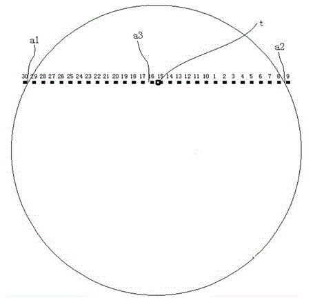
[0031] The positive and negative directions of the X direction mentioned in the present invention, as well as the forward and reverse directions of the Y direction, use the cross target of the camera image as the coordinate axis, and the positive and negative directions of the X axis correspond to the positive and negative directions of the X direction. The positive and negative directions of the Y axis correspond to the positive and negative directions of the Y direction.

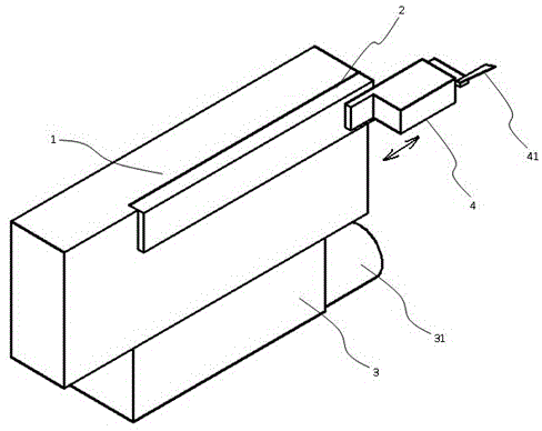
[0032] figure 1 In order to apply the test arm of the flying probe testing machine of the deviation correction method of the present invention, the above-mentioned test arm includes a main body 1, a Z-axis guide rail provided on the main body 1, and a probe device 4 movably installed on the Z-axis guide rail. The front end of the probe device 4 is provided with a probe 42 along the Z-axis direction, and a camera 3 is fixed on the underside of the main body, wherein the camera lens 31 is arranged along the ...

Embodiment 2

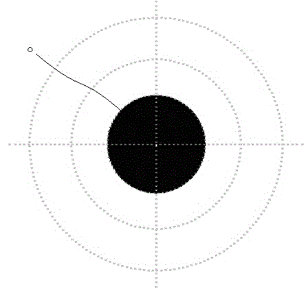
[0044] This embodiment adds the following process on the basis of step (4) of Embodiment 1: After the control system compensates the above-mentioned actual deviation value, align the center of the cross target of the camera image with the center of another test point of the PCB board to be calibrated o , the area of ​​the test point is smaller than the area of ​​the test point in step (1), repeat step (2) and step (3), use a smaller step to detect and find the center o of the test point to obtain a more accurate actual offset After the control system compensates the above actual offset again, the test is carried out. By adding the above steps, the error can be further reduced to a minimum value, ensuring that the alignment point of the camera is highly coincident with the actual needle insertion point of the probe, and the test accuracy is ensured.


PUM


Abstract

The invention discloses an error correction method of a flying probe tester. The method comprises the steps that the center of a cross target of a camera image is pointed to the center o of one test point of a PCB board to be calibrated; a probe is controlled to detect the PCB board to acquire a probe test point t; the probe test point t is taken as an initial point, and the probe is controlled to search an edge point a1 and an edge point a2 on both sides along X or Y direction; according to two detected edge points in X or Y direction, a center point a3 in X or Y direction is searched; the center point in X or Y direction is searched in the same manner, and the center point is the center o of the test point of the PCB board to be calibrated; the deviation between the probe initial point t and the center o of the test point is the actual offset of the probe to the camera center; and after a control system compensates the actual offset, a test is carried out. According to the error correction method, the actual offset of the probe to the camera center can be determined before the flying probe tester is used, and the test accuracy of the flying probe tester is ensured.

Description

technical field [0001] The invention belongs to the control field of flying probe testing machines, in particular to a deviation correction method of flying probe testing machines. Background technique [0002] Flying probe testing machine is an instrument for testing PCB boards (printed circuit boards) with high component layout, many layers, high wiring density and small distance between measuring points. It mainly tests the insulation and conduction value of circuit boards. The tester generally adopts the "true value comparison positioning method", which can monitor the test process and fault points in real time to ensure the accuracy of the test. The flying probe testing machine has the characteristics of fine pitch, not limited by the grid, flexible testing, and fast speed. [0003] like figure 1 As shown, the test arm of the flying probe testing machine is installed on the Y-axis slider of the machine base, and can move up and down in the Y direction. The Y-axis is i...

Claims


Application Information

Patent Timeline
Patent Type & Authority Applications(China)
IPC IPC(8): G01R31/28
Inventor 黄韬
Owner JOINT STARS TECH
Why Eureka
Try Eureka