Supercharge Your Innovation With Domain-Expert AI Agents!

Reverse gas infrared radiation device and reverse gas radiation method

A technology of infrared radiation and gas, which is applied in the direction of combustion methods, gas fuel burners, burners, etc., can solve the problems of unsuitable materials, incomplete combustion, and excess air, so as to suppress excessive internal temperature and solve incomplete combustion. The effect of completely eliminating the hidden danger of explosion

Active Publication Date: 2018-02-02
上海蓝炽热能科技有限公司
View PDF6 Cites 0 Cited by
  • Summary
  • Abstract
  • Description
  • Claims
  • Application Information

AI Technical Summary

Problems solved by technology

The design of the reverse gas infrared radiator needs to solve two technical problems: 1. Reverse combustion will cause the premixed gas to be poured in from above the combustion plate, how to control the balance between the input speed of the premixed gas and the combustion speed; 2. How to restrain the upward conduction of heat , control the temperature of the gas infrared radiator to prevent the premixed gas from igniting and exploding inside the radiator
[0008] This technical solution has the following negative effects: 1. The speed of airflow input is much greater than the speed of combustion, there is a lot of excess air, the combustion is incomplete, and the utilization rate of heat energy is low; 2. The power of the burner remains high, which requires low-temperature heating Dry materials are not suitable
3. The source of infrared radiation is a heated metal mesh, resulting in uneven infrared radiation
[0010] In addition, because the reverse gas infrared radiation device adopts the reverse gas method of gas supply from top to bottom, the dust particles in the air will inevitably enter the gas radiator with the combustion air, and the dust may accumulate after long-term use. As a result, the input speed of the premixed gas is affected. Once the input speed of the premixed gas is lower than the combustion speed, it will cause backfire and cause an explosion.

Method used


Image

  • Reverse gas infrared radiation device and reverse gas radiation method
  • Reverse gas infrared radiation device and reverse gas radiation method
  • Reverse gas infrared radiation device and reverse gas radiation method

Examples


Embodiment 1

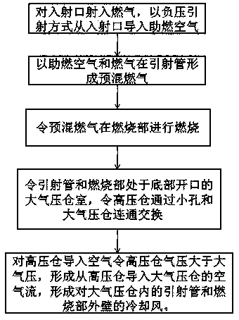
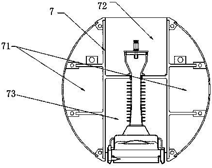
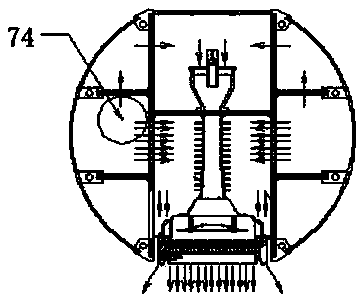
[0068] A reverse gas radiation device, including a box 7 and a radiation generator, the box 7 is installed outside the radiation generator, the radiation generator includes an entrance 1, an injection tube 2, from top to bottom, Diffusion chamber 3, combustion part 4; Injection port 1 includes gas injection port 11 and air inflow port 12, Injection port 1 is connected to an external gas supply device, and gas is injected with a low-power gas nozzle; The outer wall of injection pipe 2 includes cooling fins 23, The cooling fins 23 are uniformly distributed on the outer wall of the ejector tube 2 . The outer edge of the heat sink 23 is a circular sheet protruding; the inner side of the ejector tube 2 is a mixing part 21 and a diffusing part 22 from top to bottom, the mixing part 21 is a vertical hollow cylinder, and the diffusing part 22 is a vertical hollow cone Shaped cylinder, there is an outward inclination angle of 8° between the diffusion part 22 and the mixing part 21. Th...


PUM


Abstract

The invention discloses a reverse gas infrared radiation device and a reverse gas radiation method. The reverse gas infrared radiation device comprises a box body and a radiation generator, wherein an ejection tube and a combustion part of the radiation generator are arranged in an atmospheric pressure chamber of the box body; the atmospheric pressure chamber is communicated with a high pressure chamber; air pressure in the high pressure chamber is higher than atmospheric pressure. According to the reverse gas infrared radiation device disclosed by the invention, low-power reverse combustion is realized; through the design of the semi-closed atmospheric pressure chamber, the cooling effect on the air led into the high pressure chamber is greatly optimized.

Description

technical field [0001] The invention relates to the field of industrial heating and drying, in particular to a reverse gas infrared radiation device and a reverse gas radiation method used in industrial heating and drying. Background technique [0002] Utilizing the principle of thermal effect of infrared radiation on the resonance cracking of macromolecular water mass, it is a common technology in the field of industrial heating to evaporate and dry materials with infrared radiation. Compared with air convection drying, this technology has the advantages of low energy consumption and good drying quality. [0003] In practice, the generation methods of infrared radiation are mainly divided into two ways: electric heating ceramic plate radiation and electric heating infrared lamp tube. Both use electric energy to convert heat energy into secondary heating infrared radiation carrier. Energy is converted multiple times resulting in more energy consumption. Obviously, it is m...

Claims


Application Information

Patent Timeline
Patent Type & Authority Patents(China)
IPC IPC(8): F23D14/02F23D14/12F23D14/46
CPCF23D14/02F23D14/46
Inventor 徐进赖劲军
Owner 上海蓝炽热能科技有限公司
Features
  • R&D
  • Intellectual Property
  • Life Sciences
  • Materials
  • Tech Scout
  • Unparalleled Data Quality
  • Higher Quality Content
  • 60% Fewer Hallucinations
Learn More