
Electrical connector and method for producing electrical connector

An electrical connector and adjacency technology, which is applied to the parts, connections, and assembly/disassembly of the contact parts of the connection device, and can solve problems such as complex methods

Active Publication Date: 2015-10-14
TE CONNECTIVITY GERMANY GMBH
View PDF5 Cites 1 Cited by
  • Summary
  • Abstract
  • Description
  • Claims
  • Application Information

AI Technical Summary

Problems solved by technology

These methods are relatively complex

Method used


Image

  • Electrical connector and method for producing electrical connector
  • Electrical connector and method for producing electrical connector
  • Electrical connector and method for producing electrical connector

Examples


Embodiment Construction

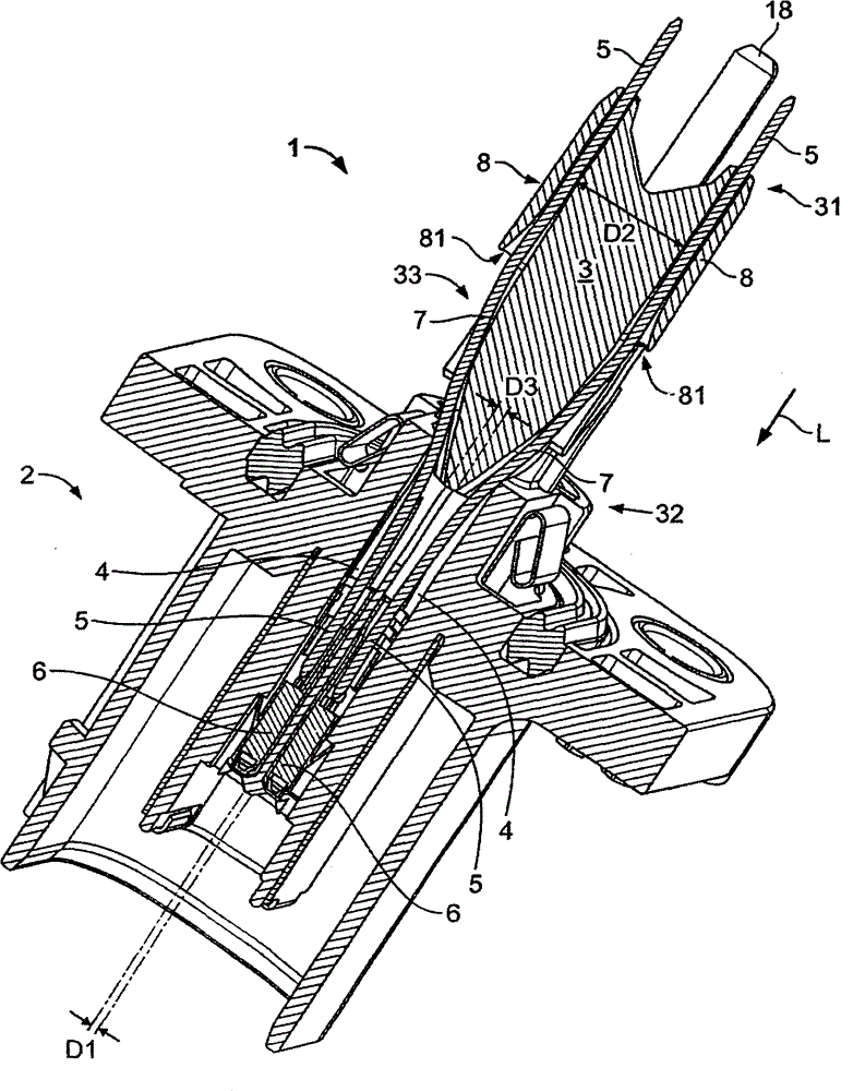
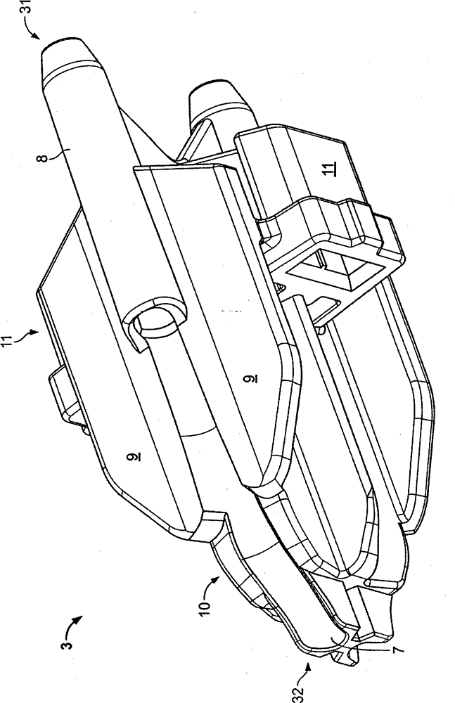
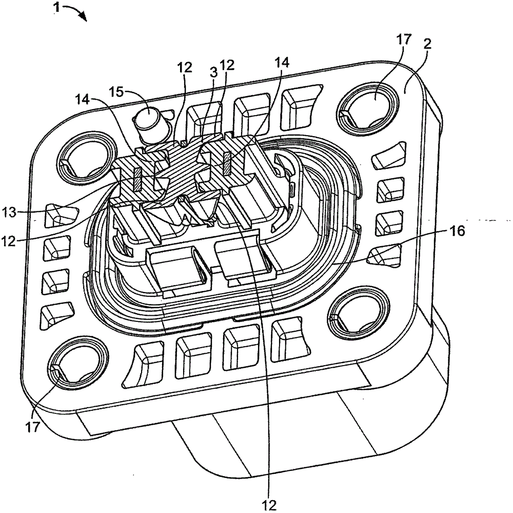
[0032] figure 1 An electrical connector 1 according to the invention is shown. It comprises a housing part 2 and an expansion part 3 .

[0033] In the housing part 2 there are two guide channels 4 for each contact element 5 . The contact elements 5 are designed as substantially rigid pins or pins and have a certain elasticity.

[0034] At the end of the contact element 5 arranged in the housing part 2, a terminal 6 in the form of a socket is mounted so that contact with a mating connector can be made in a simple manner. Alternatively, pin contacts can also be provided, for example. When it is not necessary to form a connection by plug-in, the contact element 5 can be fixed to the further conductor, for example by crimping or soldering.

[0035] The guide channels 4 extend in a linear manner and are parallel to each other in the longitudinal direction L through the housing part 2 .

[0036] The contact element 5 extends out of the housing part 2 and continues along the two...


PUM


Abstract

The invention relates to an electrical connector (1). The invention further relates to a method for producing an electrical connector (1). Electrical connectors are used in many fields. It is often necessary to change the spacing between two electrical conductors in a region of an arrangement. An object of the invention is to provide a solution which is less complex than the solutions from the prior art. This object is achieved by an electrical connector (1) having a housing portion (2) which has two guiding channels (4) which are spaced apart from each other, and having two elongate contact elements (5) which each extend through a guiding channel (4), and having a splayed member (3) which has two splayed faces (7) which are associated with the contact elements (5) and which at an end (31) facing away from the guiding channels (4) have a larger spacing from each other than the guiding channels (4), wherein the splayed member (3) tapers in the direction towards the guiding channels (4). In a method according to the invention for producing an electrical connector (1), the splayed member (3) is moved in the direction of the housing portion (2) and the contact elements (5) are thereby splayed open.

Description

technical field [0001] The invention relates to an electrical connector. The invention further relates to a method for manufacturing an electrical connector. Background technique [0002] Electrical connectors are used in various fields. It is often necessary to vary the spacing between two electrical conductors in the area of ​​the device. There are several ways to achieve this goal. In the first method, flexible conductors such as cables are used. The disadvantage of this situation is that, in order to contact the flexible conductor, other components need to be mounted to the conductor, for example when the conductor is intended to be soldered to a board. In another prior art method, a rigid conductor is bent into the proper form and then inserted. In a third method, the rigid conductors are manufactured to form, eg stamped from sheet metal into the correct form. These methods are relatively complex. Contents of the invention [0003] The object of the invention i...

Claims


Application Information

Patent Timeline
IPC IPC(8): H01R13/516H01R13/40H01R43/20
CPCH01R13/502H01R13/4367H01R13/533H01R43/00H01R43/22Y10T29/49204H01R43/20
Inventor M·利斯廷S·西格特
Owner TE CONNECTIVITY GERMANY GMBH
Features
  • Generate Ideas
  • Intellectual Property
  • Life Sciences
  • Materials
  • Tech Scout
  • Unparalleled Data Quality
  • Higher Quality Content
  • 60% Fewer Hallucinations
Learn More