Strong pull fastening structure

A joint structure and tensioning technology, which is applied in the direction of foundation structure engineering, construction, sheet pile walls, etc., can solve problems such as large gaps and slippage, achieve the effect of reducing moving gaps, reducing connection gaps, and improving work efficiency

Active Publication Date: 2015-10-28
周兆弟
View PDF5 Cites 3 Cited by
  • Summary
  • Abstract
  • Description
  • Claims
  • Application Information

AI Technical Summary

Problems solved by technology

However, this scheme also has a fly in the ointment: the outer part of the splice is smooth, and it will slip when it is snap-fitted with the snap ring, thereby forming a free stroke and causing a large gap between the two piles

Method used


Image

  • Strong pull fastening structure
  • Strong pull fastening structure
  • Strong pull fastening structure

Examples


Embodiment 1

[0025] like Figure 4 and Figure 5 As shown, a strong pull fastening structure includes an intermediate nut 1 and a plug connector 2 inserted into the intermediate nut 1. The end of the intermediate nut 1 has a collar 4 composed of several cards 3. When the plug connector 2 When inserted into the middle nut 1, the collar 4 can clamp the plug joint 2 so that the plug joint 2 and the middle nut 1 snap fit, and the inside of the card 3 has at least one locking tooth 5,

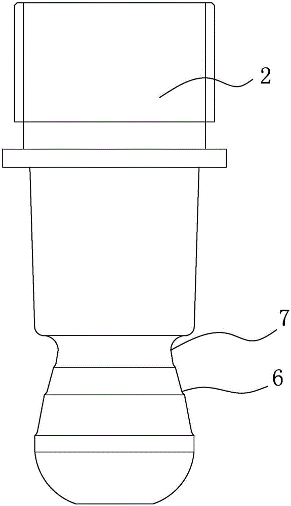
[0026] recombine image 3 As shown, the plug joint 2 has at least one tensioning step 6 , and the tensioning step 6 can snap fit with the locking teeth 5 to form a stepped buckling structure 10 .

[0027] Specifically, the end of the plug connector 2 has a concave portion 7 matching the shape of the collar 4 , and the tension step 6 is located on the outer wall of the concave portion 7 . The stretching step 6 is in the shape of a ring, and the teeth 5 on the plurality of cards 3 are enclosed to form a ring st...

Embodiment 2

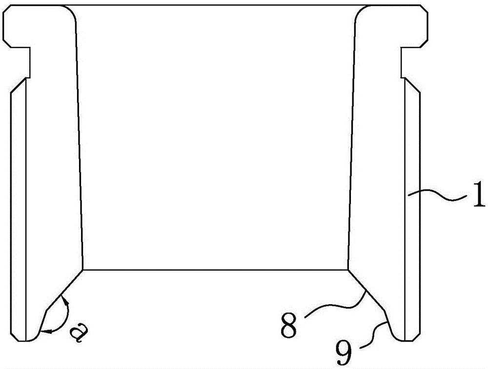
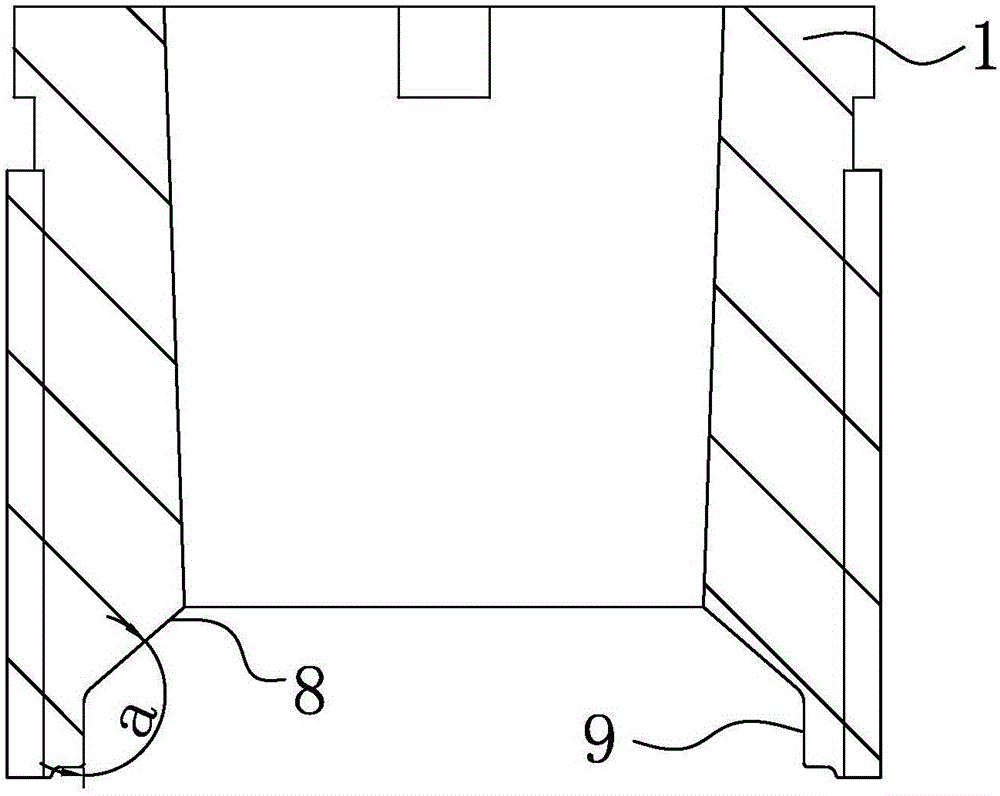
[0036] The structure and working principle of this embodiment are basically the same as that of Embodiment 1, the difference is that, as figure 1 and figure 2 As shown, the end of the middle nut 1 has a collar positioning cavity 8 that can place the collar 4, and the end of the collar positioning cavity 8 has a function that can block the clamp when the collar 4 slides to the end of the collar positioning cavity 8. The collar 4 prevents the collar 4 from slipping out of the collar limiting cavity 9 of the collar positioning cavity 8 .

[0037] The inclinations of the outer wall of the collar positioning cavity 8 and the outer wall of the collar limiting cavity 9 are different. The angle a between the outer wall of the collar positioning cavity 8 and the outer wall of the collar limiting cavity 9 is an obtuse angle. Preferably, the obtuse angle a is between 130° and 150°.

[0038] Image 6 It is a schematic diagram of the structure of the intermediate nut in the prior art....


PUM


Abstract

The invention belongs to the technical field of building components, relates to a strong pull fastening structure, and solves the technical problem of unreliable connection in the prior art. The strong pull fastening structure comprises a middle nut, and a connecting plug inserted in the middle nut, wherein the end part of the middle nut has a clamping ring consisting of multiple clamping pieces; and when the connecting plug is inserted in the middle nut, the clamping ring can clamp the connecting plug to enable the connecting plug and the middle nut are in clamping fit. The strong pull fastening structure is characterized in that the clamping pieces have at least one clamping tooth inside; the connecting plug has at least one tension step; and the tension steps can be clamped with the clamping teeth to form a step type fastening structure. The tension steps can fit the clamping teeth to form the step type fastening structure, so that a moving gap of the connecting plug can be decreased, a connecting gap between pile bodies can be reduced, and the connection is closer and more reliable.

Description

technical field [0001] The invention belongs to the technical field of building components, and relates to a strong pull buckle joint structure. Background technique [0002] The two ends of the existing prefabricated prefabricated piles are provided with steel plates, and the square piles are connected by mutual welding between the steel plates. After the connected pile body is pressed into the ground when the pile is pressed, because the soil contains salt, especially chlorine salt, it will corrode the steel plate exposed to the soil, resulting in the fracture of the connection between the pile and the pile, thus making the connection Pile disconnected. In addition, the way of connecting by welding of steel plates is relatively complicated, and the connection is inconvenient. Therefore, people provide a method for connecting with a connector, and the use of the connector greatly improves the connection speed and strength between prefabricated parts, and can also prevent ...

Claims


Application Information

Patent Timeline
IPC IPC(8): E02D5/30E02D5/52
Inventor 周兆弟
Owner 周兆弟
Why Eureka
Try Eureka