Strong buckle structure
A joint structure and tensioning technology, which is applied in the direction of foundation structure engineering, construction, sheet pile walls, etc., can solve problems such as slippage and large gaps, and achieve the effect of reducing movement gaps, reducing connection gaps, and tight and reliable connections
- Summary
- Abstract
- Description
- Claims
- Application Information
AI Technical Summary
Problems solved by technology
Method used
Image
Examples
Embodiment 1
[0025] Such as Figure 4 with Figure 5 As shown, a strong pull fastening structure includes an intermediate nut 1 and a plug connector 2 inserted into the intermediate nut 1. The end of the intermediate nut 1 has a collar 4 composed of several cards 3. When the plug connector 2 When inserted into the middle nut 1, the collar 4 can clamp the plug joint 2 so that the plug joint 2 and the middle nut 1 snap fit, and the inside of the card 3 has at least one locking tooth 5,
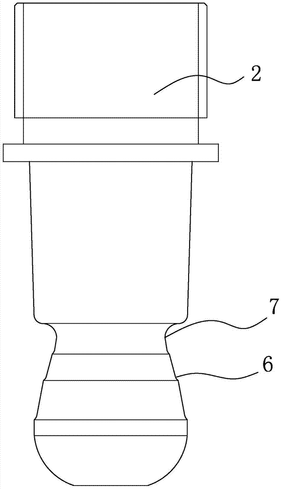
[0026] recombine image 3 As shown, the plug joint 2 has at least one tensioning step 6 , and the tensioning step 6 can snap fit with the locking teeth 5 to form a stepped buckling structure 10 .
[0027] Specifically, the end of the plug connector 2 has a concave portion 7 matching the shape of the collar 4 , and the tension step 6 is located on the outer wall of the concave portion 7 . The stretching step 6 is in the shape of a ring, and the teeth 5 on the plurality of cards 3 are enclosed to form a rin...
Embodiment 2
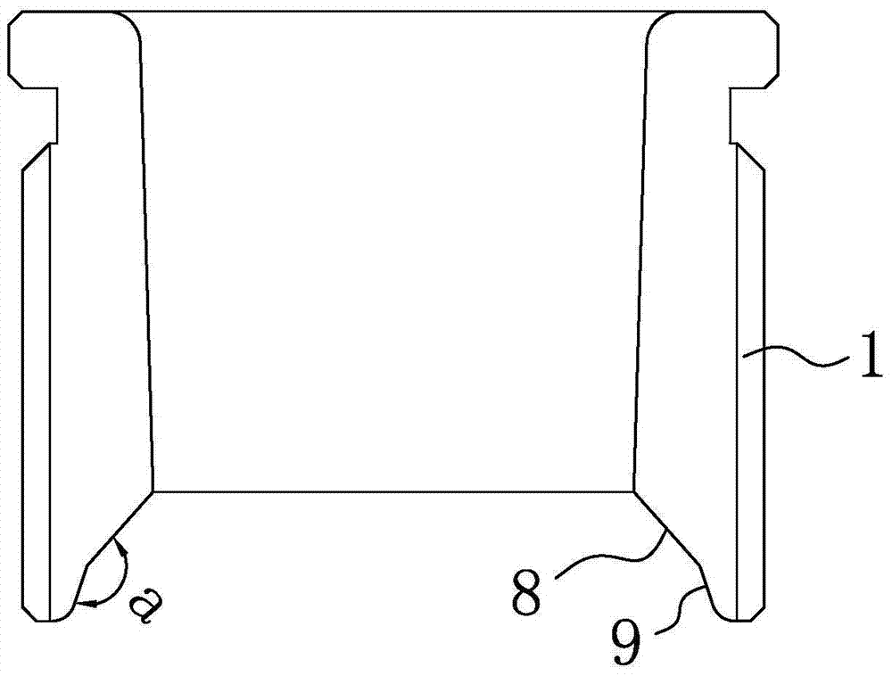
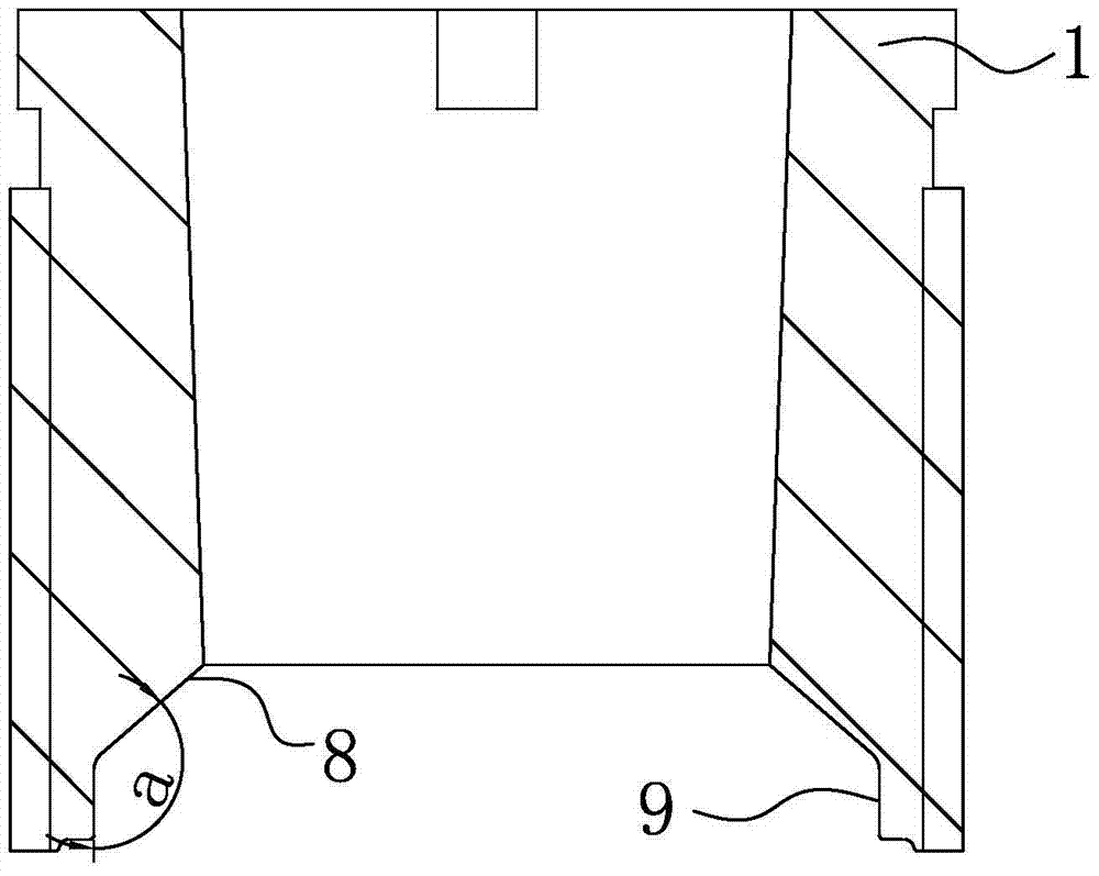
[0036] The structure and working principle of this embodiment are basically the same as that of Embodiment 1, the difference is that, as figure 1 with figure 2 As shown, the end of the middle nut 1 has a collar positioning cavity 8 that can place the collar 4, and the end of the collar positioning cavity 8 has a function that can block the clamp when the collar 4 slides to the end of the collar positioning cavity 8. The collar 4 prevents the collar 4 from slipping out of the collar limiting cavity 9 of the collar positioning cavity 8 .
[0037] The inclinations of the outer wall of the collar positioning cavity 8 and the outer wall of the collar limiting cavity 9 are different. The angle a between the outer wall of the collar positioning cavity 8 and the outer wall of the collar limiting cavity 9 is an obtuse angle. Preferably, the obtuse angle a is between 130° and 150°.
[0038] Image 6 It is a schematic diagram of the structure of the intermediate nut in the prior art...
PUM
 Abstract
Description
Claims
Application Information
 - R&D
- Intellectual Property
- Life Sciences
- Materials
- Tech Scout
- Unparalleled Data Quality
- Higher Quality Content
- 60% Fewer Hallucinations
Browse by: Latest US Patents, China's latest patents, Technical Efficacy Thesaurus, Application Domain, Technology Topic, Popular Technical Reports.
© 2025 PatSnap. All rights reserved.Legal|Privacy policy|Modern Slavery Act Transparency Statement|Sitemap|About US| Contact US: help@patsnap.com


