Mud densimeter and fluid filling method for mud test

A mud density and density meter technology, which is applied to determine the specific gravity and other directions by measuring the pressure difference, can solve the problems of large volume, poor measurement accuracy, cumbersome structure, etc., and achieve the effects of reliable transportation, good sealing, and convenient installation and use.

Inactive Publication Date: 2011-04-20
TIANJIN KENTAI INSTR
View PDF3 Cites 1 Cited by
  • Summary
  • Abstract
  • Description
  • Claims
  • Application Information

AI Technical Summary

Problems solved by technology

[0003] In view of the problems existing in the prior art, the purpose of the present invention is to solve the problem of the existing mud density meter with simple structure, poor measurement accuracy, bulky size and structure by providing a novel, all-welded mud density meter structure for mud testing. The lack of bulkiness, and in the mud density meter, the digital circuit technology is applied to realize the parameter measurement of the mud density through the amplifier circuit, the microprocessor, the three input buttons on the shell assembly and the HART hand-operated device; through the design The unique digital display head achieves convenient and timely observation of on-site test results; the fully welded structure ensures good sealing and high reliability, ensuring reliable use in a wide range of operating temperatures and most dangerous industrial conditions. A mud density meter for mud testing and a fluid filling method that tends to be rationalized and humanized in design and can realize remote monitoring and maintenance

Method used


Image

  • Mud densimeter and fluid filling method for mud test
  • Mud densimeter and fluid filling method for mud test
  • Mud densimeter and fluid filling method for mud test

Examples


Embodiment Construction

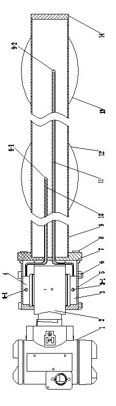
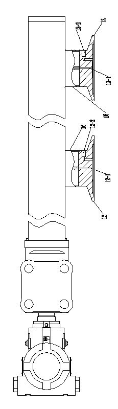
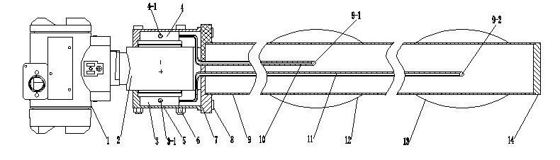
[0016] Such as figure 1 , 2 As shown, the mud density meter used for mud testing includes shell assembly 1, differential pressure sensor 2, positive connection seat 3, negative connection seat 4, capillary tube I10, capillary tube II11, membrane seat assembly I12, membrane seat assembly II13 , which is characterized in that: it also includes a chamber 5, a plate 7, a tube 9, a disc 14, a straight cylinder I15, and a straight cylinder II16, and the positive connection seat 3 and the negative connection seat 4 are respectively connected to the positive and negative sides of the differential pressure sensor 2. The tube 9 is welded together with the plate 7, the straight cylinder I15, the straight cylinder II16 and the disk 14 respectively, the membrane seat assembly I12 and the membrane seat assembly II13 are respectively welded on the straight cylinder I15 and the straight cylinder II16, and the capillary One end of Ⅰ10 and capillary Ⅱ11 passes through the holes Ⅰ9-1 and Ⅱ9-2 o...


PUM


Abstract

The invention relates to a mud densimeter and a fluid filling method for a mud test. A positive connecting base and a negative connecting base of the densimeter are respectively welded to a positive direction and a negative direction of a differential pressure transducer, a pipe is respectively welded to a plate, two straight barrels and a disc, two membrane base assemblies are respectively welded on two straight barrels, one ends of two capillaries respectively pass through the plate and two holes on the inner wall of the plate to be welded to a fluid pipe I and a fluid pipe II, the other end of the capillary I is welded and fixed on the negative connecting base and communicated with a filling hole I, the other end of the capillary II is welded and fixed with the positive connecting base and communicated with a filling hole II, the differential pressure transducer is arranged in an accommodating chamber and fixed to the accommodating chamber with screws, the accommodating chamber and the plate are fixed together with screws, and a shell assembly and the differential pressure transducer are fixed together. The mud densimeter is of a full welded structure, has good sealing performance, long service life and high reliability, is reliable to transport and convenient to move and remount, and satisfies the requirement for current market on a high-accuracy intelligent mud densimeter.

Description

technical field [0001] The present invention relates to a density meter, in particular to a mud density meter for mud testing and a fluid filling method, which is suitable for predicting lost circulation and blowout in oil exploration and well logging, judging abnormal phenomena of downhole mud density and other high temperature Density measurement of flow liquids and static liquids in pipes and pipes in most dangerous industrial places, with hygienic requirements or process fluids that are easy to accumulate and condense. Background technique [0002] Mud is the fluid used in drilling and is commonly measured with a mud density meter. During drilling, the formation pressure is balanced by adjusting the mud density, so as to prevent and deal with accidents such as blowout (surge), lost circulation and well collapse. The existing mud density meter adopts the combined structure of stop valve, sampling barrel and sampling valve, which has a simple structure and poor measuremen...

Claims


Application Information

Patent Timeline
IPC IPC(8): G01N9/26
Inventor 王洪明周佩霞崔国永刘玉
Owner TIANJIN KENTAI INSTR
Why Eureka
Try Eureka