Electric control scanning waveguide leaky-wave antenna based on liquid crystal

A technology of leaky wave antenna and scanning wave, which is applied in the direction of leaky waveguide antenna, antenna, circuit, etc., can solve the problem that the electronically controlled scanning leaky wave antenna is difficult to work, and achieve the effects of low loss, convenient perfusion, and simple control mechanism

Active Publication Date: 2015-10-28
北京超材信息科技有限公司
View PDF6 Cites 21 Cited by
  • Summary
  • Abstract
  • Description
  • Claims
  • Application Information

AI Technical Summary

Problems solved by technology

[0006] The purpose of the present invention is to solve the problem that the traditional electronically controlled scanning leaky-wave antenna based on traditional electronically adjustable components such as varactor diodes is difficult to work in the microwave high-frequency band and that the existing liquid crystal electronically controlled scanning leaky-wave antenna needs a specially designed bias circuit. An electronically controlled scanning waveguide leaky wave antenna based on liquid crystal is provided

Method used


Image

  • Electric control scanning waveguide leaky-wave antenna based on liquid crystal
  • Electric control scanning waveguide leaky-wave antenna based on liquid crystal
  • Electric control scanning waveguide leaky-wave antenna based on liquid crystal

Examples


specific Embodiment approach 1

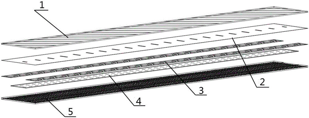
[0031] Specific implementation mode one: the following combination Figure 1 to Figure 4 Describe this embodiment mode, the electronically controlled scanning waveguide leaky wave antenna based on liquid crystal described in this embodiment mode, it comprises top dielectric plate layer 1, metal layer 2, insulating adhesive layer 3, liquid crystal layer 4 and bottom waveguide groove 5;

[0032] The lower surface of the top dielectric plate layer 1 is provided with a metal layer 2. The metal layer 2 is a leaky wave structure etched with periodic transverse slits. The periodic transverse slits allow electromagnetic waves to propagate between the bottom waveguide groove 5 and the metal layer 2. When the equivalent series inductance increases;

[0033] The top dielectric plate layer 1 and the metal layer 2 are tightly integrated into one body through mechanical processing, electroplating, hot pressing or microelectronic technology;

[0034] The bottom waveguide groove 5 is a recta...

specific Embodiment approach 2

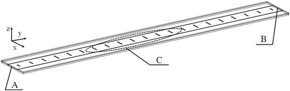
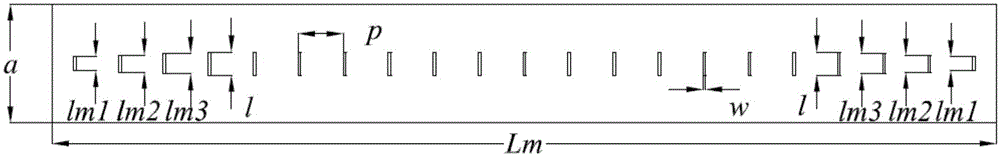
[0042] Specific implementation mode two: the following combination Figure 5 to Figure 15 This implementation mode is described, and the antenna structure of the first implementation mode is further described in this implementation mode in combination with specific examples.

[0043] As a special case, Figure 5 and Figure 6 The specific design parameters of a liquid crystal waveguide transverse slot leaky wave electronically controlled scanning antenna working at 10 GHz are given. Depend on Figure 5 , the top dielectric layer 1 is a microwave substrate, and the relative permittivity ε r =4, loss tangent tanδ=0.004, thickness d 2 =1mm, the thickness of the metal layer 2 is 0.017mm. The antenna is composed of N=18 periodic slot units, and the unit spacing p=15mm. The length of the main transverse slit radiating unit is l=6mm, the length of the first three and the last three slit units is l m3 , l m2 , l m1 The sequence is: 6mm, 5mm, 4mm, and the width of all the gaps...


PUM


Abstract

The invention provides an electric control scanning waveguide leaky-wave antenna based on liquid crystal, belongs to the technical field of microwave antenna engineering, and aims at solving problems that a conventional electric control scanning leaky-wave antenna based on a varactor and other conventional electrically controlled elements is difficult to work at a microwave high-frequency band, and existing liquid crystal electric control scanning leaky-wave antennas require the special design of a bias circuit. The electric control scanning waveguide leaky-wave antenna comprises a top part dielectric plate layer, a metal layer, an insulation paste layer, a liquid crystal layer and a bottom part waveguide slot. The metal layer is arranged at the lower surface of the top part dielectric plate layer. The metal layer has a leaky-wave structure with etching of periodic transverse seams. Equivalent series inductance of electromagnetic wave is enabled to be increased by the periodic transverse seams when electromagnetic wave is transmitted between the bottom part waveguide slot and the metal layer. The metal layer is provided with N periodic seam units. Seam unit spacing distance p is from lambdag / 2 to lambdag. The seams of the middle part are main radiation units. Seam length l of the main radiation unit is from lambdag / 4 to lambdag / 2. The former four and the latter four seams are auxiliary radiation units.

Description

technical field [0001] The invention belongs to the technical field of microwave antenna engineering. It can be widely used in modern wireless mobile communication, satellite communication in motion and various radar systems. Background technique [0002] Since the leaky wave antenna was proposed by W.W.Hansen in the 1940s, its unique radiation characteristics and excellent lobe scanning characteristics have made the leaky wave antenna a hot spot in the field of antenna research. The original leaky wave antenna is composed of a slotted rectangular waveguide, and its essence is that when the electromagnetic wave propagating on the waveguide structure is a fast wave, it will radiate part of the electromagnetic wave to the space. In recent decades, research on leaky-wave antennas has developed rapidly, especially planar leaky-wave antennas have been widely studied, because planar leaky-wave antennas can be directly processed on printed circuit boards (PCBs), with low profile, ...

Claims


Application Information

Patent Timeline
Patent Type & Authority Applications(China)
IPC IPC(8): H01Q13/20H01Q3/00
Inventor 孟繁义
Owner 北京超材信息科技有限公司
Why Eureka
Try Eureka