Anti-rolling water tanks with side ports and anti-rolling method thereof

A technology for anti-rolling water tanks and water tanks, which is applied in the direction of reducing the movement of ships through displacement, which can solve the problems of strong air compressibility, structural damage, not suitable for large-tonnage ships, etc., and achieve easy operation, control devices and transmission devices. simple effect

Inactive Publication Date: 2015-11-18
HEBEI UNIV OF ENG
View PDF6 Cites 5 Cited by
  • Summary
  • Abstract
  • Description
  • Claims
  • Application Information

AI Technical Summary

Problems solved by technology

The former is not suitable for large tonnage ships and tankers due to the limitation of water valve size
Moreover, the water hammer effect caused by the rapid opening and closing of the water valve will damage the structure
The latter due to the strong compressibility of the air, the control accuracy is not high
The common disadvantage of these two forms of U-shaped passive controllable anti-rolling water tanks is that there must be enough space on the ship to arrange waterways and airways, which brings a lot of inconvenience to the design and construction of anti-rolling water tanks
At the same time, when the anti-rolling water tank is used to reduce the pitching of the ship, it is difficult to designate space for the arrangement of water channels and air channels

Method used


Image

  • Anti-rolling water tanks with side ports and anti-rolling method thereof
  • Anti-rolling water tanks with side ports and anti-rolling method thereof
  • Anti-rolling water tanks with side ports and anti-rolling method thereof

Examples


Embodiment Construction

[0016] Below the present invention will be further described in conjunction with the embodiment in the accompanying drawing:

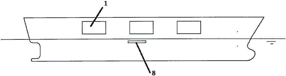
[0017] Such as figure 1 As shown, it includes the right cabin door 1 and the pressure sensor 8.

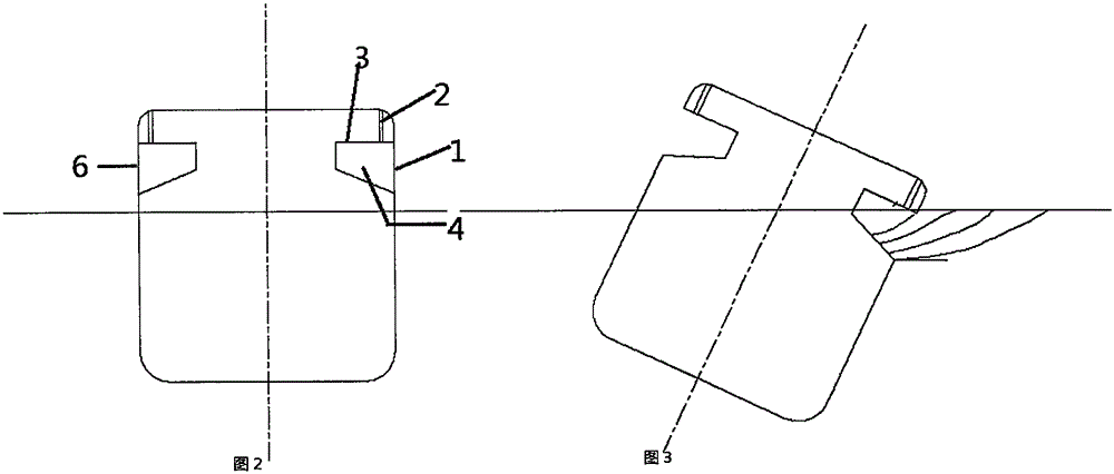
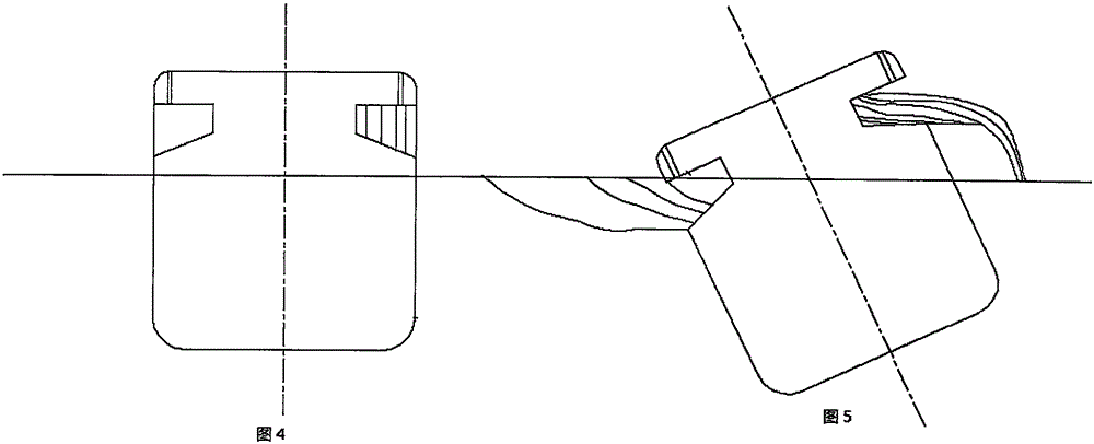
[0018] Such as figure 2 Shown, comprise the cabin 4 of anti-rolling water tank, left cabin door 6, water tank exhaust and drainage pipe 2, water tank roof 3.

[0019] Such as Figure 8 As shown, it includes a rotating shaft 5 , a rotor 7 , a drive shaft 13 , a controller 9 , an angular velocity control gyro 10 , and a discontinuous longitudinal bulkhead 14 .

[0020] Such as Figure 10 As shown, it includes ribs 11 on the cabin door and openings 12 on the ribs.

[0021] Described below is the working principle and operation process of the anti-rolling water tank of the present invention.

[0022] Such as figure 1 As shown, left and right symmetrical water tanks are set on both sides of the ship, and front and rear symmetrical water tanks are set at...


PUM


Abstract

Provided are anti-rolling water tanks with side ports and an anti-rolling method thereof. One or more pairs of the anti-rolling water tanks are arranged on the left side and the right side of the bow and / or the stern; each water tank comprises a compartment, the right side port and the left side port, the top of each compartment is provided with a compartment roof, and a water tank exhaust pipeline and a water tank drainage pipeline are arranged on the upper portion of each compartment roof; the left side ports of the port and the right side ports of the starboard are arranged above the hull waterline, the right side ports and the left side ports are connected with hull sides through rotating shafts, the right side ports and the left side ports can be opened or closed freely through the rotating shafts, after the right side ports and the left side ports are closed, the water tanks have the water-resisting property, and the water tank exhaust pipelines and the water tank drainage pipelines are arranged on the upper portions of the water tanks; the hull is internally provided with a rotor, the rotating shafts, a driving shaft, a control shaft, a pressure sensor, a controller and an angular speed gyroscope, wherein the rotating shafts are driven by the rotor to rotate, the rotor drives the control shaft through the driving shaft, the driving shaft is perpendicularly meshed with the control shaft, the pressure sensor is located below the portion, near the corresponding rotating shaft, of the water tank of the side of the hull, the angular speed gyroscope is connected with the controller, and the rotor, the pressure sensor and the angular speed gyroscope are all connected with the controller.

Description

(1) Technical field [0001] The invention relates to a controllable anti-rolling water tank, in particular to an open anti-rolling water tank structure provided with a hatch used in the low-speed running of a ship, and a ship anti-rolling method. (2) Background technology [0002] The anti-rolling water tank is one of the effective devices to reduce the roll of the ship, and has been widely used in various ships. The working principle of the anti-rolling water tank is to use the moment generated by the water level difference between the two sides of the anti-rolling water tank to resist the wave moment when the ship rolls under the action of the environmental load, so as to realize the anti-rolling of the ship. The premise of anti-rolling water tank anti-rolling is the principle of double resonance anti-rolling, that is: the natural frequency of the water in the water tank, the natural frequency of the ship’s roll, and the frequency of the wave disturbance moment are equal, a...

Claims


Application Information

Patent Timeline
Patent Type & Authority Applications(China)
IPC IPC(8): B63B39/03
Inventor 李彦苍赵捷黄山齐晓蒙王杰郝文超郑博
Owner HEBEI UNIV OF ENG
Why Eureka
Try Eureka