Diffuse type flameless burner

A technology of flameless combustion and combustion-supporting air, which is applied in the direction of burners, gas fuel burners, combustion methods, etc., and can solve the problems that flameless burners cannot meet the combustion requirements

Inactive Publication Date: 2015-12-16
罗诺克兹(北京)能源设备技术有限公司
View PDF6 Cites 2 Cited by
  • Summary
  • Abstract
  • Description
  • Claims
  • Application Information

AI Technical Summary

Problems solved by technology

[0004] The embodiment of the present invention provides a diffused flameless burner to solve the problem that the flameless burner in the prior art cannot meet the combustion requirements under different power conditions

Method used


Image

  • Diffuse type flameless burner

Examples


Embodiment Construction

[0020] Hereinafter, the present invention will be described in detail with reference to the drawings and examples. It should be noted that, in the case of no conflict, the embodiments of the present invention and the features in the embodiments can be combined with each other.

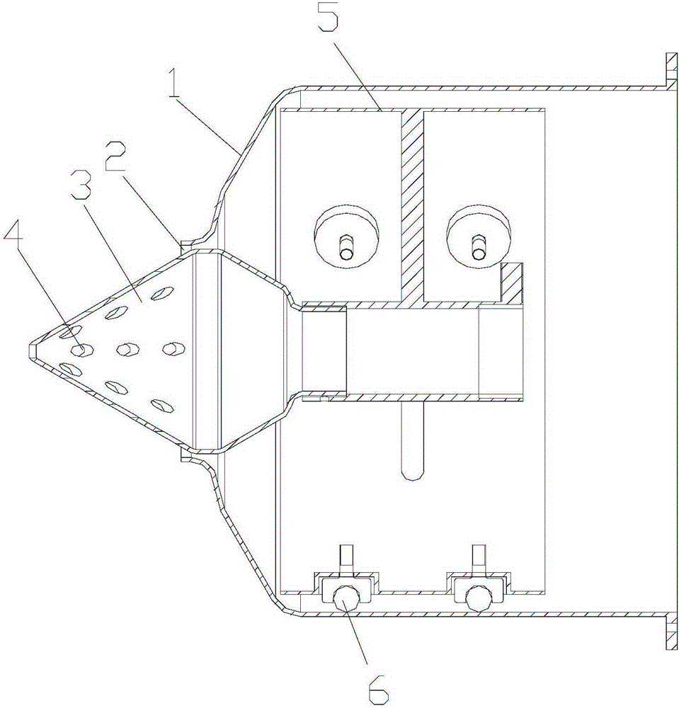
[0021] see figure 1 As shown, this embodiment provides a diffused flameless burner, including a housing 1 and a nozzle 3, the housing 1 has a combustion air outlet 2; the nozzle 3 is movably arranged at the combustion air outlet 2 to adjust the combustion air outlet 2 Outlet area. Here, the air outlet area of ​​the combustion air outlet 2 refers to the air outlet area of ​​the annular gap between the outer wall of the nozzle 3 and the inner wall of the combustion air outlet 2 .

[0022] Through the movable nozzle 3 relative to the combustion-supporting air outlet 2, the gap between the nozzle 3 and the combustion-supporting air outlet 2 can be adjusted, and then the air outlet area of ​​the combustio...


PUM


Abstract

The embodiment of the invention discloses a diffuse type flameless burner. The diffuse type flameless burner comprises a shell (1) and a spraying head (3), wherein the shell (1) is provided with a combustion-supporting air outlet (2), and the spraying head (3) is movably arranged at the combustion-supporting air outlet (2) to adjust the air outlet area of the combustion-supporting air outlet (2). According to the diffuse type flameless burner, the problem that in the prior art, a flameless burner cannot meet the combustion requirements under different power situations is solved.

Description

technical field [0001] The invention relates to the technical field of combustion equipment, in particular to a diffused flameless burner. Background technique [0002] Flameless combustion is a new type of combustion with extremely high thermal efficiency and almost zero pollutant emissions. [0003] Since the existing flameless burners are all high-speed jet burners, a certain speed is required to maintain flameless combustion. Therefore, the existing flameless burners can only maintain their design power under the condition of flameless combustion. , unable to adjust the power, and unable to meet the combustion requirements under different power conditions. Contents of the invention [0004] The embodiment of the present invention provides a diffused flameless burner to solve the problem that the flameless burner in the prior art cannot meet the combustion requirements under different power conditions. [0005] In order to solve the above problems, the embodiment of t...

Claims


Application Information

Patent Timeline
Patent Type & Authority Applications(China)
IPC IPC(8): F23D14/02F23D14/48F23D14/64
Inventor 牟从莹
Owner 罗诺克兹(北京)能源设备技术有限公司
Why Eureka
Try Eureka