H-shaped mixing pile equipment

A technology of mixing piles and equipment, which is applied in the direction of sheet pile walls, buildings, foundation structure engineering, etc., and can solve problems such as the inability to form H-shaped mixing piles

Inactive Publication Date: 2015-12-23
朱艳菊
View PDF4 Cites 281 Cited by
  • Summary
  • Abstract
  • Description
  • Claims
  • Application Information

AI Technical Summary

Problems solved by technology

[0002] At present, the mixing pile equipment used in building foundation engineering is to use one or more drilling heads to rotate and cut the so

Method used


Image

  • H-shaped mixing pile equipment
  • H-shaped mixing pile equipment
  • H-shaped mixing pile equipment

Examples


Embodiment Construction

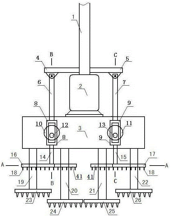
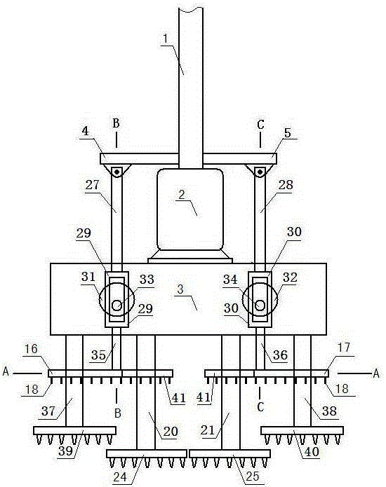
[0015] Accompanying drawing is a kind of specific embodiment of the present invention, and the lower end of main pole 1 of this embodiment is fixed motor 2 upper end, and motor lower end is provided with driving box 3, and the lower end of driving box outputs agitating shaft one 19, agitating shaft two 20, agitating shaft three 21 , stirring shaft four 22, stirring shaft five 37, stirring shaft six 38, the stirring shaft lower end is provided with stirring drill bit 1 23, the stirring shaft 2 lower end is provided with stirring drill bit 2 24, the stirring shaft 3 lower end is provided with stirring drill bit 3 25, stirring Axle four lower ends are provided with stirring drill bit four 26, stirring shaft five lower ends are provided with stirring drill bit five 39, and stirring shaft six lower ends are provided with stirring drill bit six 40; the right end of cross bar one and the left end of cross bar two are respectively fixed on main rod; The front left part of the case is p...


PUM


Abstract

Disclosed is H-shaped mixing pile equipment. Mixing arms are fixed to the front portion and the rear portion of the right portion of a first large square frame respectively, a plurality of second tool teeth are arranged in the direction, facing a second mixing shaft, of the two mixing arms respectively, and the lower portions of the two mixing arms are each provided with a plurality of first tool teeth. Mixing arms are fixed to the front portion and the rear portion of the left portion of a second large square frame respectively, a plurality of second tool teeth are arranged in the direction, facing a third mixing shaft, of the two mixing arms respectively, and the lower portions of the two mixing arms are each provided with a plurality of first tool teeth. A plurality of second tool teeth are arranged in a frame body of the first large square frame, and a plurality of first tool teeth are arranged on the lower portion of the frame body of the first large square frame. A plurality of second tool teeth are arranged in a frame body of the second large square frame, and a plurality of first tool teeth are arranged on the lower portion of the frame body of the second large square frame.

Description

technical field [0001] The invention relates to a stirring pile device, in particular to an H-shaped stirring pile device used in building foundation engineering. Background technique [0002] At present, the mixing pile equipment used in building foundation engineering is to use one or more drilling heads to rotate and cut the soil and mix with cement slurry to form a circular pile or a lapped body of multiple circular piles, which cannot form an H-shaped mixing Pile body. Contents of the invention [0003] The present invention makes up for the above shortcomings and provides an H-shaped stirring pile equipment. [0004] The present invention is achieved through the following technical solutions: [0005] An H-shaped stirring pile equipment, the lower end of the main rod is fixed to the upper end of the motor, the lower end of the motor is provided with a drive box, and the lower end of the drive box outputs the first stirring shaft, the second stirring shaft, the thir...

Claims


Application Information

Patent Timeline
IPC IPC(8): E02D5/46
Inventor 朱艳菊
Owner 朱艳菊
Why Eureka
Try Eureka