PCB (printed circuit board) unloader

A technology for PCB boards and triggers, applied in the direction of conveyor objects, lamination auxiliary operations, lamination, etc., can solve the problems of complex structure of the unloading machine, inability to achieve stable removal of adhesive strips, and incomplete tearing of glue, etc.

Active Publication Date: 2015-12-30
JIANGSU BVM INTELLIGENT TECH
View PDF9 Cites 13 Cited by
  • Summary
  • Abstract
  • Description
  • Claims
  • Application Information

AI Technical Summary

Problems solved by technology

The structure of the existing unloading machine is complicated, and the glue is not completely removed, so

Method used


Image

  • PCB (printed circuit board) unloader
  • PCB (printed circuit board) unloader
  • PCB (printed circuit board) unloader

Examples


Embodiment Construction

[0032] The present invention will now be further described in detail in conjunction with the accompanying drawings and embodiments. These drawings are all simplified schematic diagrams, only illustrating the basic structure of the present invention in a schematic manner, so it only shows the composition related to the present invention.

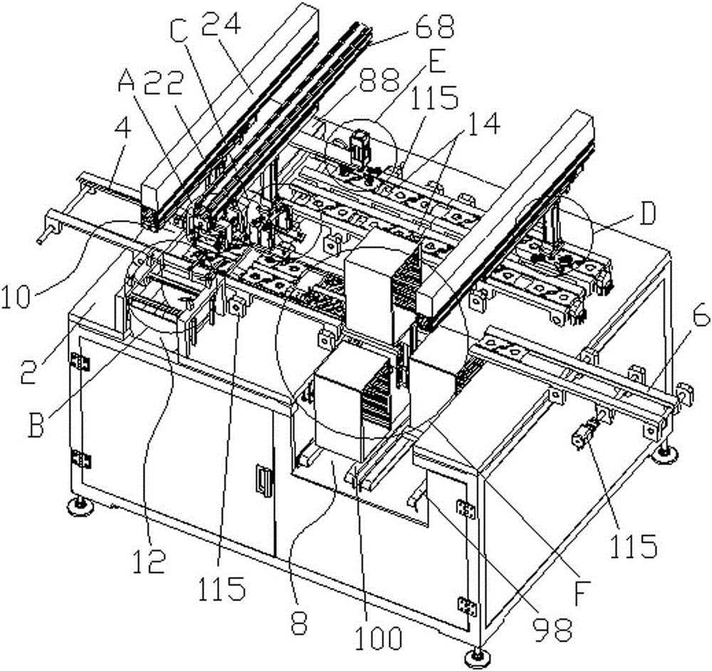
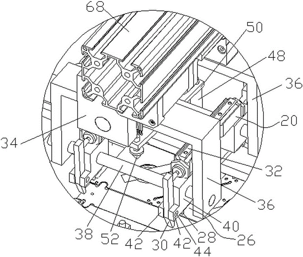
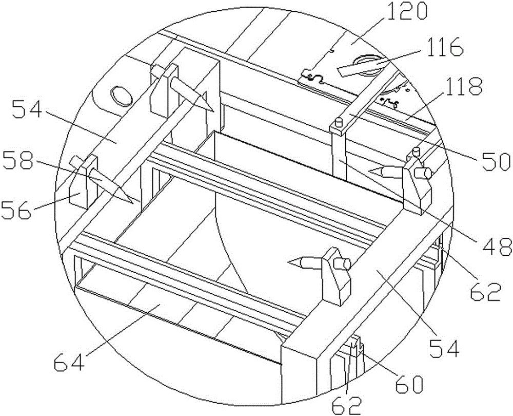
[0033] Such as figure 1 , figure 2 , Figure 4 , Figure 5 , Figure 8-Figure 11 As shown, a PCB board unloading machine includes a frame 2, a loading track 4 installed on the frame 2, a blanking track 6, and an unloading device 8 between the loading track 4 and the blanking track 6, The top of the feeding track 4 is provided with a glue tearing device 10, an outer side of the feeding track 4 is provided with a removal device 12, and the other outer side of the feeding track 4 is provided with at least one buffer track 14, and the top of the buffer track 14 is provided with The first transfer manipulator 16 and the second transfer manipu...


PUM


Abstract

The invention relates to a PCB (printed circuit board) unloader, which comprises a rack, a loading track and a blanking track arranged on the rack, and an unloading device arranged between the loading track and the blanking track. An adhesive tearing device is arranged above the loading track; one outer side of the loading track is provided with a removal device, and the other outer side of the loading track is provided with at least one buffering track; a first shifting manipulator and a second shifting manipulator are arranged above the buffering track. According to the PCB unloader, four position adhesive tearing chucks cooperate and independently locate a pressing device, so as to ensure that adhesive tearing is smooth and successful; through triple protections of chuck non-stick processing, initiative strikingoff and pneumatic blowing shifting, the stable removal of an adhesive tape is realized; a PCB carrier card box circulates among three positions, so non-stop line carrier gathering is realized; the three-position card box circularly cooperates with a two-position ion fan to performing cooling, so each carrier is enabled to be subjected to enough cooling; buffering of an adhesive tape-tore PCB adopts a double-buffering track mode, and when abnormity exists between a previous stop and a later stop, the PCB automatically enters the buffering mode, so a previous section-carrier cannot be caused to flow out to stop the line.

Description

technical field [0001] The invention relates to a board unloading machine, in particular to a PCB board unloading machine. Background technique [0002] The PCB board needs to go through this process during processing. The adhesive strip on the PCB board that flows out of the previous process is torn off, and the PCB board is removed from the carrier and placed on the flow line of the next process. The structure of the existing lowering machine is complicated, and the glue is not completely removed, so the stable removal of the glue strip cannot be realized, and the equipment does not run smoothly. Contents of the invention [0003] The invention overcomes the disadvantages of the prior art and provides a PCB unloading machine with a simple structure. [0004] In order to achieve the above object, the technical solution adopted in the present invention is: a PCB board unloading machine, including a frame, a loading track installed on the frame, a blanking track, and a An...

Claims


Application Information

Patent Timeline
IPC IPC(8): B65G47/90B32B38/10
Inventor 李相鹏
Owner JIANGSU BVM INTELLIGENT TECH
Why Eureka
Try Eureka