Supercharge Your Innovation With Domain-Expert AI Agents!

Fluid pumping device with split flow structure

A fluid and structural technology, applied in the field of pneumatic tools, can solve problems such as reducing the strength of the container

Inactive Publication Date: 2018-01-12
JEN SIAN IND
View PDF6 Cites 0 Cited by
  • Summary
  • Abstract
  • Description
  • Claims
  • Application Information

AI Technical Summary

Problems solved by technology

[0004] The improved front-opening technology can control the inflow of high-pressure gas through the inflow end, but in general use, there is usually no additional air pressure adjustment mechanism between the upper-opening fluid pumping device and the high-pressure gas source. Therefore, the high-pressure gas The flow rate entering the container is limited, and the pressure of the gas entering the container is still very high, and the expansion of the container cannot be completely avoided. Even though it has been equipped with a safety valve for pressure relief, the activation of the safety valve requires a Above the set minimum starting pressure, before reaching the starting pressure, the safety valve will not actuate, and the expansion of the container cannot be avoided. In addition, such containers are generally made of polymer materials. After use, the repeated expansion that still exists in the previous improvement technology means that the container itself is still repeatedly subjected to external forces, which is easy to reduce the strength of the container itself, and it is easy to cause cracks, and there is still a need for improvement. And when the pressure value inside the container is near the minimum starting pressure value, because the pressure in the container is not constant, it will also cause the safety valve to start and close repeatedly, which will affect the use.

Method used


Image

  • Fluid pumping device with split flow structure
  • Fluid pumping device with split flow structure
  • Fluid pumping device with split flow structure

Examples


Embodiment Construction

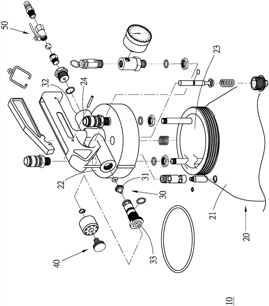
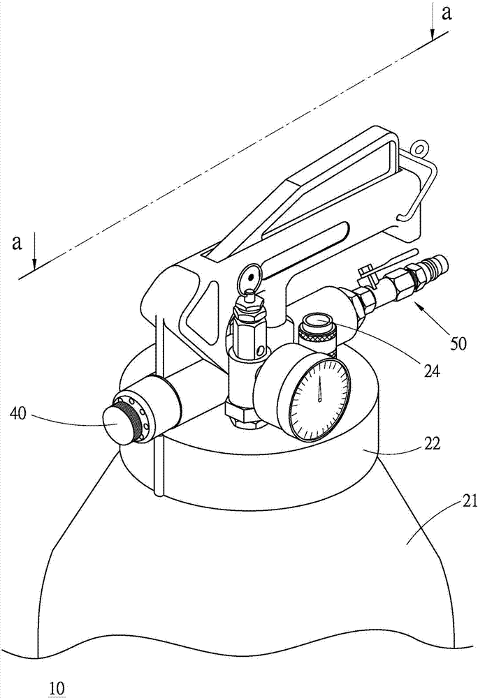
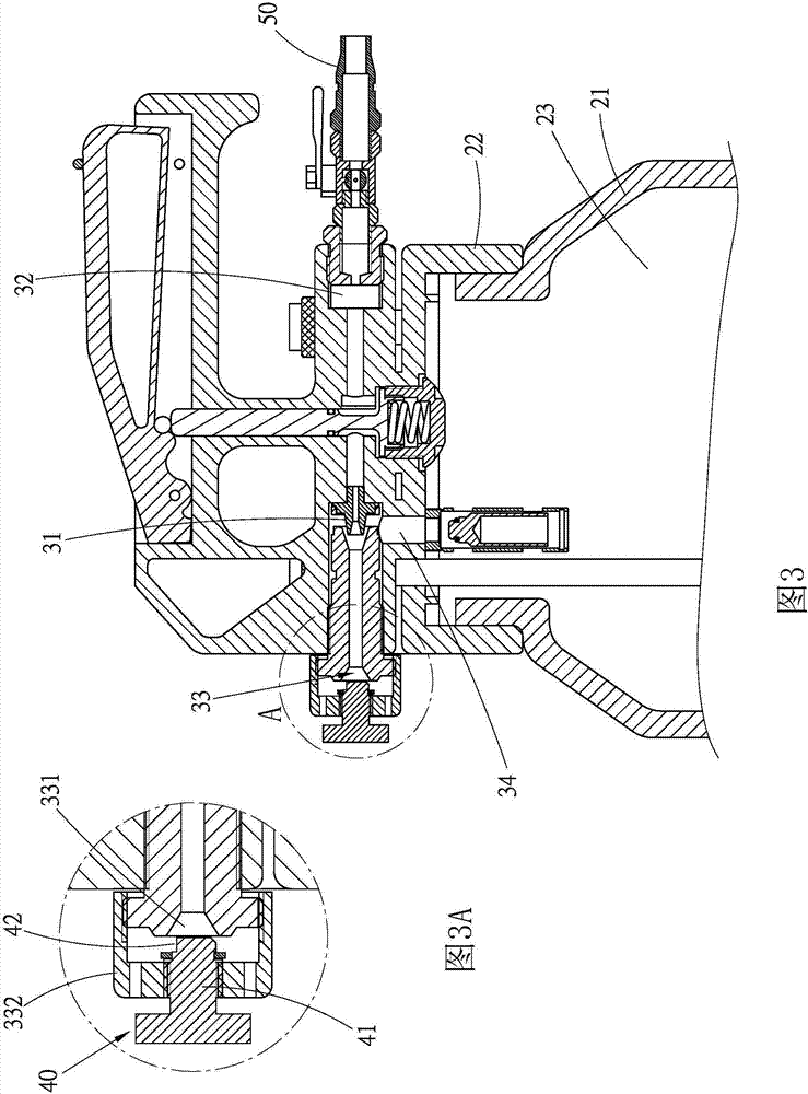
[0031] First, see Figure 1 to Figure 4 and Figure 4A As shown, the fluid pumping device 10 provided in the first preferred embodiment of the present invention with a split flow structure is the same as that disclosed in the No. 098222559 Model Patent, but the difference is that it will be disclosed in this embodiment The diversion structure of the new patent is unprecedented. Specifically, the fluid pumping device 10 with the diversion structure mainly includes a container 20, a pressure difference generating part 30, a gas blocking part 40 and an air inlet part. 50.

[0032] This container 20 has a barrel body 21 with a hollow top and a hollow top, and a barrel cover 22 that can close the top opening of the barrel body 21, so that the top opening of the barrel body 21 can be closed by the barrel cover 22, so that the barrel body 21 The inner chamber 23 is closed, and a tubular material inlet 24 communicates with the interior and exterior of the chamber 23 .

[0033] The ...


PUM


Abstract

The fluid pumping device with a decompression structure provided by the present invention enables the fluid pumping device to maintain communication between an air outlet end of the fluid pumping device and the atmosphere when the fluid pumping device is discharging the fluid in the container, so that the air outlet end is in the shape of Incomplete sealing, whereby the high-pressure gas entering the interior of the fluid pumping device forms a pressurized flow and a discharge flow, and the discharge flow is guided to the atmosphere through the gas outlet port.

Description

technical field [0001] The present invention is related to pneumatic tool technology, in particular to a fluid pumping device with split flow structure. Background technique [0002] According to the fluid pumping device developed on the basis of the Venturi tube principle, many different specific technical contents have been disclosed in the known technology. The fluid pumping device specifically provides a control gas flow path in the venturi tube, thereby providing the use function of suction and discharge, and greatly improving the convenience of operation. [0003] Furthermore, the prior patent No. 098222559 in Taiwan, China focuses on the perspective of industrial safety, and further improves the aforementioned known fluid pumping device to change the external high-pressure gas in response to the use status of the known fluid pumping device. The flow rate of the inflow, when using the known fluid pumping device to suck the external fluid into the container, the inflow...

Claims


Application Information

Patent Timeline
Patent Type & Authority Patents(China)
IPC IPC(8): F04F5/14
Inventor 庄嘉琼
Owner JEN SIAN IND
Features
  • R&D
  • Intellectual Property
  • Life Sciences
  • Materials
  • Tech Scout
  • Unparalleled Data Quality
  • Higher Quality Content
  • 60% Fewer Hallucinations
Learn More