Cervical and lumbar treatment traction bed

A technology of cervical and lumbar spine and traction bed, which is applied in the fields of physical therapy, medical science, fracture, etc., and can solve the problems of easy fatigue, poor traction treatment effect, and inaccurate control of traction force

Active Publication Date: 2016-02-03
JIANGSU RIXIN MEDICAL EQUIP
View PDF7 Cites 15 Cited by
  • Summary
  • Abstract
  • Description
  • Claims
  • Application Information

AI Technical Summary

Problems solved by technology

The disadvantages of the currently used cervical and lumbar treatment traction beds are: (1) when performing lumbar traction treatment, the back board can only move back and forth relative to the leg board, and at the same time the leg board can only swing up and down and left and right relative to the back board, It is impossible to form traction on all directions of the lumbar spine, and the effect of traction treatment is poor; (2) During the traction treatment of the cervical spine, the traditional traction method of pulling the patient upward in a sitting position is still used, and the traction force cannot be precisely controlled. Sitting posture, easy to fatigue, unable to keep the cervical spine in a relaxed state, and the effect of traction therapy is poor

Method used


Image

  • Cervical and lumbar treatment traction bed
  • Cervical and lumbar treatment traction bed
  • Cervical and lumbar treatment traction bed

Examples


Embodiment Construction

[0013] The present invention will be further described below in conjunction with the accompanying drawings and specific embodiments.

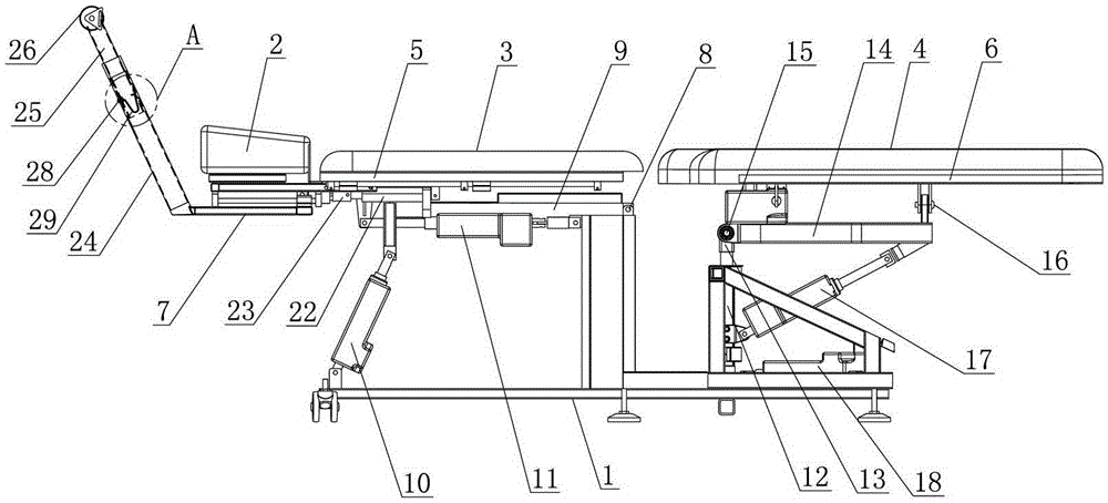
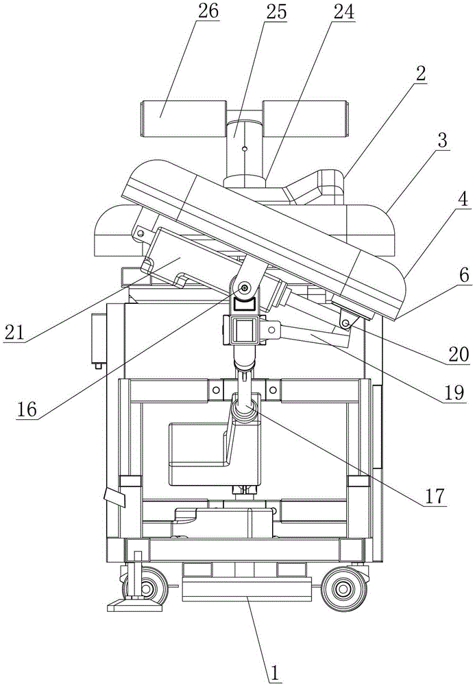
[0014] Such as figure 1 , figure 2 , image 3 As shown, the cervical and lumbar treatment traction bed includes: a base 1, a headrest 2, a back plate 3 and a leg plate 4, and the base 1 is provided with a front base frame 5 and a rear base frame which are distributed in front and rear intervals. The frame 6, the headrest 2 and the back plate 3 are fixedly arranged on the top of the front base frame 5, the leg board 4 is arranged on the top of the rear base frame 6, and the front base frame 5 can synchronously drive the head under the drive of the front drive mechanism. The pillow 2 and the back plate 3 swing up and down or move forward and backward relative to the leg plate 4. In this embodiment, the structure of the front driving mechanism is: the rear end is hinged by a first horizontal axis 8 in the left and right direction. On the front...


PUM


Abstract

The invention discloses a cervical and lumbar treatment traction bed, which comprises a base, wherein a front base frame and a rear base frame are arranged on the base; a head pillow and a backboard are arranged on the front base frame, and leg boards are arranged on the rear base frame; the front base frame, driven by a front driving mechanism, can drive the head pillow and the backboard to simultaneously swing up and down or to move fore and forth relative to the leg boards, and the rear base frame, driven by a rear driving mechanism, can drive the leg boards to swing up and down or left and right or to rotate left and right relative to the head pillow and the backboard; a neck traction rod mounting frame, which is capable of moving fore and forth relative to the front base frame, is arranged at the front end of the base frame in a sliding mode; a neck traction rod, which is located at the front of the head pillow, is arranged on the neck traction mounting frame; a first forward-rearward translation push rod motor is arranged at the bottom of the front base frame; a push rod of the first forward-rearward translation push rod motor is connected to the neck traction rod mounting frame by virtue of a tension sensor; and the neck traction rod can be driven by the tension sensor and the neck traction rod to move fore and forth relative to the head pillow. The traction bed disclosed by the invention has the advantage of being good in traction treatment effect.

Description

technical field [0001] The invention relates to equipment for treating cervical and lumbar vertebrae, in particular to a traction bed for treating cervical and lumbar vertebrae. Background technique [0002] The structure of the existing cervical and lumbar treatment traction bed is: including the back board and the leg board, the front drive assembly for driving the back board to move back and forth relative to the leg board, and the front drive assembly for driving the leg board to swing up and down relative to the back board and left and right. Oscillating rear drive assembly. The disadvantages of the currently used cervical and lumbar treatment traction beds are: (1) when performing lumbar traction treatment, the back board can only move back and forth relative to the leg board, and at the same time the leg board can only swing up and down and left and right relative to the back board, It is impossible to form traction on all directions of the lumbar spine, and the effe...

Claims


Application Information

Patent Timeline
Patent Type & Authority Applications(China)
IPC IPC(8): A61F5/042A61H1/02
Inventor 周建平
Owner JIANGSU RIXIN MEDICAL EQUIP
Why Eureka
Try Eureka