
Electric locomotive and current collector

An electric locomotive and current collector technology, applied in the field of electric locomotive equipment and current collectors, can solve the problems of inability to change the collector head, increase the current receiving area, ablation, etc.

Active Publication Date: 2016-02-03
ZHUZHOU ELECTRIC LOCOMOTIVE CO LTD
View PDF5 Cites 8 Cited by
  • Summary
  • Abstract
  • Description
  • Claims
  • Application Information

AI Technical Summary

Problems solved by technology

Due to the swaying of the car body or the laying error of the current receiving rail, the collector head may not fit in a large area with the current receiving rail, resulting in arcing or ablation
[0003] At present, the current collecting head of the current collector is assembled with a single degree of freedom, and it is impossible to change the angle of the current receiving surface of the current collector when the surface of the current receiving rail has an angular deviation to maximize the fit with the current receiving rail and increase the current receiving area.

Method used


Image

  • Electric locomotive and current collector
  • Electric locomotive and current collector
  • Electric locomotive and current collector

Examples


Embodiment Construction

[0022] The present application provides a current collector, which realizes providing a current collector that can more flexibly fit the current receiving rail. The present application also provides an electric locomotive including the above current collector.

[0023] The technical solutions in the embodiments of the present application will be clearly and completely described below in conjunction with the accompanying drawings in the embodiments of the present application. Obviously, the described embodiments are only some of the embodiments of the present application, not all of them. Based on the embodiments of the present application, all other embodiments obtained by persons of ordinary skill in the art without making creative efforts belong to the protection scope of the present application.

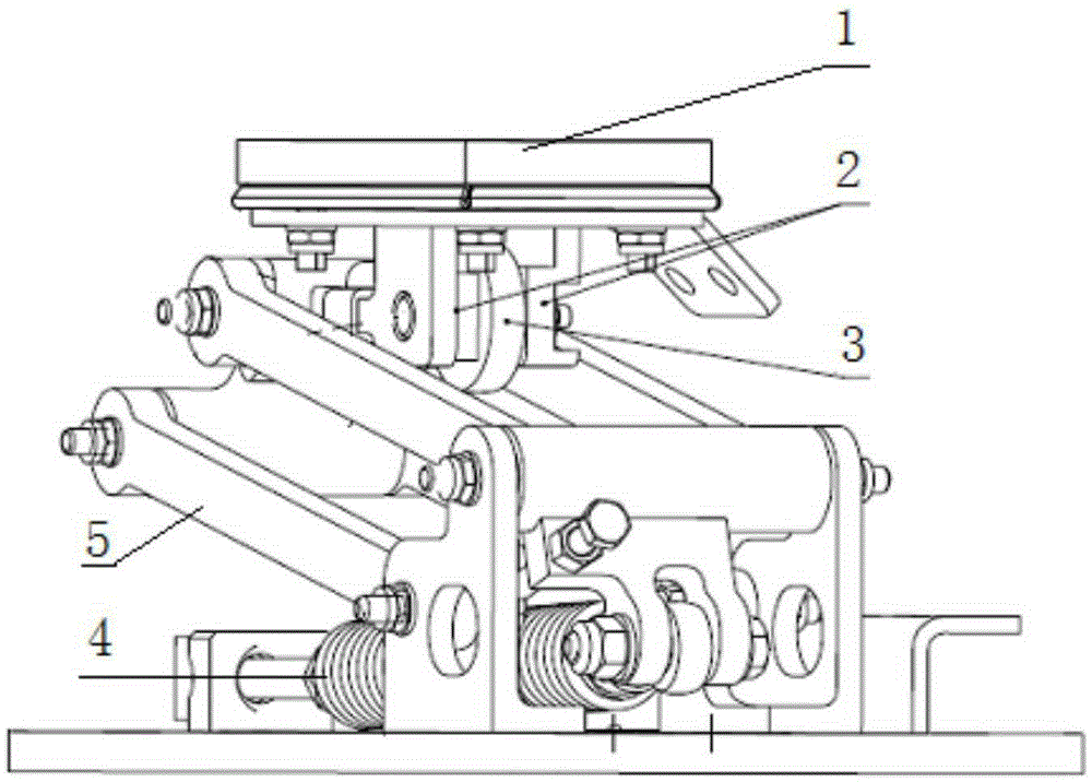
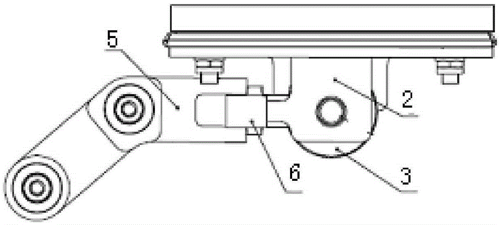
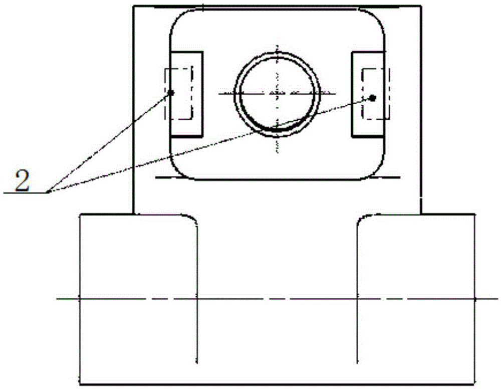
[0024] figure 1 Schematic diagram of the current collector provided for this application; figure 2 A schematic diagram of the connection structure between the current collector...


PUM


Abstract

The invention provides a current collector. The current collector comprises a base, a frame, an elastic connecting piece, an universal head connecting part and a trolley head, wherein the base is mounted on an electric locomotive; the frame is arranged on the base; the universal head connecting part is arranged at the upper end of the frame; one end of an universal head of the universal head connecting part is connected with the bottom of the trolley head; and the elastic connecting piece is arranged between the base and the frame, and is used for hoisting the trolley head at the upper end of the frame to be contacted with a current collecting rail. The base is fixedly mounted on the electric locomotive; the elastic connecting piece is located in a stretching or extending state to pull or eject the frame; and the trolley head is upwards support to press against the current collecting rail by the universal head connecting part on the frame. As the universal head connecting part is adopted to connect with the trolley head, the trolley head can realize three-degree-of-freedom rotation, that is, the trolley head can rotate around X axis, Y axis and Z axis; and the provision of the current collector more flexibly bonded with the current collecting rail is realized. The invention further provides an electric locomotive including the current collector.

Description

technical field [0001] The present application relates to the technical field of electric locomotive equipment, and more specifically, relates to a current collector. The present application also relates to an electric locomotive comprising the above current collector. Background technique [0002] The collector head is in contact with the current receiving rail to transmit the current on the current receiving rail to the vehicle. Due to the swaying of the car body or the laying error of the current receiving rail, the collector head may not fit in a large area with the current receiving rail, resulting in arcing or ablation. [0003] At present, the current collecting head of the current collector is assembled with a single degree of freedom, and it is impossible to change the angle of the current receiving surface of the current collector when the surface of the current receiving rail has an angular deviation to maximize the fit with the current receiving rail and increas...

Claims


Application Information

Patent Timeline
Patent Type & Authority Applications(China)
IPC IPC(8): B60L5/22B60L5/28
Inventor 索建国周洁林平李军罗维张海丰陈敏坚冯叶郭瑾玉王秋红孙宁
Owner ZHUZHOU ELECTRIC LOCOMOTIVE CO LTD
Learn More