A power distribution self-protection circuit applied to missile equipment

A self-protection circuit and equipment technology, which is applied in the direction of circuit devices, emergency power supply arrangements, electrical components, etc., can solve problems such as the inability of the power supply circuit on the bomb to provide working power for equipment, system energy loss, etc.

Active Publication Date: 2017-11-21
中国航天科技集团公司第四研究院第四十一研究所
View PDF3 Cites 0 Cited by
  • Summary
  • Abstract
  • Description
  • Claims
  • Application Information

AI Technical Summary

Problems solved by technology

If this phenomenon occurs after the missile is launched, it will lead to serious consequences
In order to ensure that the signal continues to be effective, there must be a certain working incentive to maintain the signal, which will inevitably cause a certain degree of system energy loss, and if the contactor itself has a fault and cannot be controlled to pull in, it will also cause the power supply to pop up The circuit cannot normally provide working power for each device

Method used


Image

  • A power distribution self-protection circuit applied to missile equipment

Examples


Embodiment Construction

[0026] The present invention will be described in detail below with reference to the accompanying drawings and embodiments.

[0027] The specific implementation method of "a power distribution self-protection circuit applied to a bomb-mounted device" of the present invention is given below.

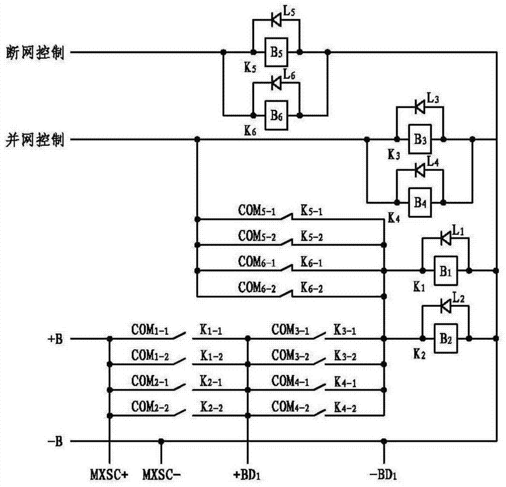
[0028] like figure 1 As shown, the power distribution self-protection circuit in this embodiment includes six electromagnetic relays K 1 , K 2 , K 3 , K 4 , K 5 and K 6 , six freewheeling diodes L 1 , L 2 , L 3 , L 4 , L 5 and L 6 .

[0029] For electromagnetic relays, it includes multiple sets of normally open contacts and normally closed contacts, and each common terminal corresponds to a set of normally open contacts and a set of normally closed contacts. You can select it on the contact and its common terminal.

[0030] Electromagnetic relay K 1 Has wire package B 1 , normally open contact K1-1 and its corresponding public terminal COM 1-1 , and the normally open cont...


PUM


Abstract

The invention discloses a power distribution self-protection circuit applied to bomb-on equipment, which realizes self-protection or cutting off of the power supply signal of the bomb-on equipment according to control instructions; it includes electromagnetic relays K1-K6, and each relay includes two groups of normally open contact and two sets of normally closed contacts; the disconnection control signal is connected to the positive terminals of wire packages B5 and B6, and the negative terminals of wire packages B1~B6 are connected to the negative signal of power supply; the negative signal of the main power supply is connected to the negative signal of power supply To the negative signal of the bus bar; after the common terminals COM5-1, COM5-2, COM6-1 and COM6-2 are short-circuited, they are connected to the grid-connected control signal and the positive terminals of the wire packages B3 and B4; the normally closed contact K5- 1. K5‑2, K6‑1, K6‑2, and the normally open contacts K3‑1, K3‑2, K4‑1, K4‑2 are short-circuited, and then connected to the positive ends of wire packages B1 and B2; public Terminals COM1‑1, COM1‑2, COM2‑1 and COM2‑2 are short-circuited and connected to the positive signal of the power supply and the positive signal of the bus bar; the normally open contacts K1‑1, K1‑2, K2‑1 and K2‑ 2 After short-circuiting, connect to the positive signal of the main power supply; after short-circuiting the common terminals COM3-1, COM3-2, COM4-1 and COM4-2, connect to the positive signal of the main power supply.

Description

technical field [0001] The invention belongs to the technical field of launch control, and in particular relates to a power distribution self-protection circuit applied to missile equipment. Background technique [0002] With the rapid development of electronic technology, the integration of analog-to-digital circuits is increasing day by day, the technical strength and functions of missile-borne equipment are increasing day by day, and the complexity is also getting higher and higher. There must be sufficient energy provided to each equipment on the missile for perform their respective functions. Generally, before the missile is launched, the ground test equipment or the pre-launch control equipment shall apply the ground power supply to provide working power for the equipment on the missile; after the missile is launched, the main power supply on the missile shall provide working power for the equipment on the missile. The main power supply, also known as the primary powe...

Claims


Application Information

Patent Timeline
Patent Type & Authority Patents(China)
IPC IPC(8): H02J9/04
Inventor 王晓晖陈纲张光喜张佳兴胡博纪浩李凯丰白平
Owner 中国航天科技集团公司第四研究院第四十一研究所
Why Eureka
Try Eureka