Image coding method and device

An image coding and coding technology, applied in the field of image coding methods and devices, can solve problems such as poor coding performance and inability to generate current blocks, and achieve the effects of improving coding compression efficiency and efficiency

Inactive Publication Date: 2016-02-03
TENCENT TECH (SHENZHEN) CO LTD
View PDF8 Cites 1 Cited by
  • Summary
  • Abstract
  • Description
  • Claims
  • Application Information

AI Technical Summary

Problems solved by technology

However, in some images, the current block cannot be generated by the pixel values ​​of adjacent rows and / or columns according to various modes of intra-frame prediction, and poor coding performance will be obtained.

Method used


Image

  • Image coding method and device
  • Image coding method and device
  • Image coding method and device

Examples


Embodiment Construction

[0025] The following will clearly and completely describe the technical solutions in the embodiments of the present invention with reference to the accompanying drawings in the embodiments of the present invention. Obviously, the described embodiments are only some of the embodiments of the present invention, not all of them. Based on the embodiments of the present invention, all other embodiments obtained by persons of ordinary skill in the art without making creative efforts belong to the protection scope of the present invention.

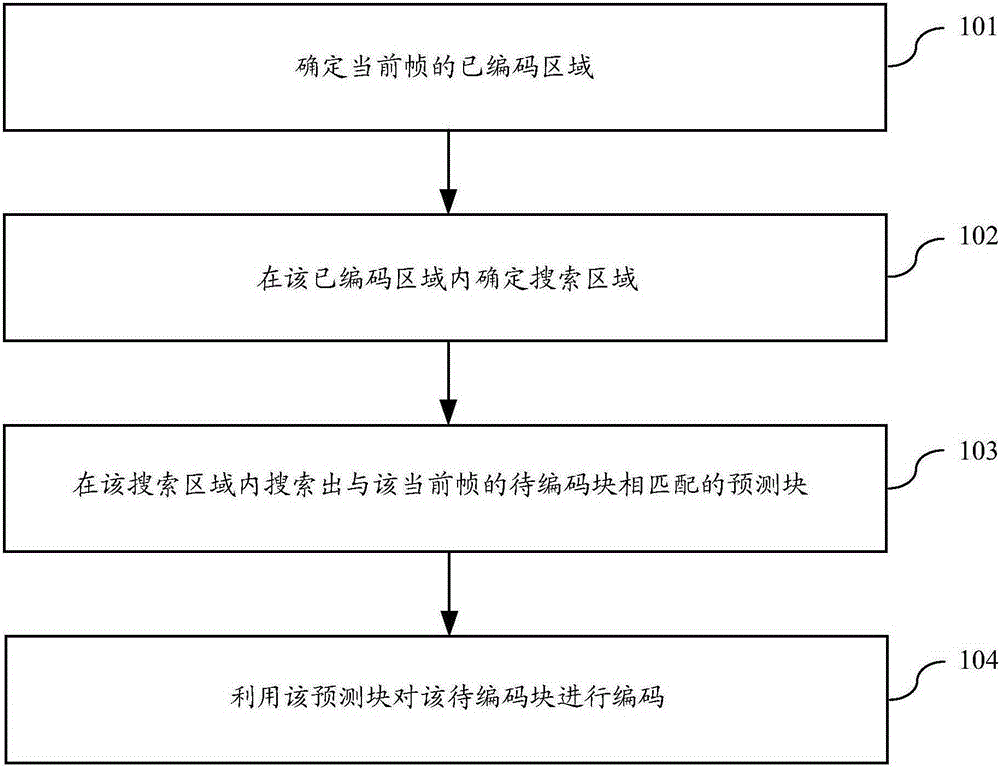
[0026] figure 1 It is a schematic flowchart of an image encoding method in an embodiment of the present invention. Such as figure 1 As shown, the method includes the following steps.

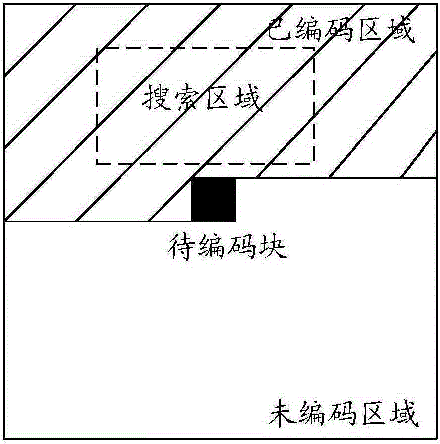
[0027] Step 101, determine the coded area of ​​the current frame.

[0028] Step 102, determine a search area within the coded area.

[0029] Step 103, searching for a predicted block matching the block to be encoded in the current frame within the search area. ...


PUM


Abstract

The application discloses an image coding method and device. The method comprises: determining a coded area of a current frame; determining a search area in the coded area; searching for a prediction block matching a block to be coded of the current frame in the search area; and utilizing the prediction block to code the block to be coded. The image coding method and device can improve image coding efficiency.

Description

technical field [0001] The present invention relates to the technical field of image processing, in particular to an image coding method and device. Background technique [0002] The currently used intra-frame prediction technology utilizes spatial correlation to realize pixel prediction. Specifically, the current block is predicted by weighting adjacent pixel values, such as pixel values ​​in the upper row, left column, upper left corner, and upper right corner. This intra-frame prediction method can remove the spatial redundancy between adjacent blocks and obtain a better compression effect. However, in some images, the current block cannot be generated from the pixel values ​​of adjacent rows and / or columns according to multiple modes of intra-frame prediction, and poor coding performance will be obtained. Contents of the invention [0003] Embodiments of the present invention provide an image encoding method and device, which are used to improve image encoding effici...

Claims


Application Information

Patent Timeline
IPC IPC(8): H04N19/593H04N19/567H04N19/105
Inventor 王曜
Owner TENCENT TECH (SHENZHEN) CO LTD
Why Eureka
Try Eureka